Photoelectric conversion element, image reading device, image forming apparatus, image reading method, and computer-readable recording medium

a technology of image reading and conversion element, which is applied in the direction of color television details, television system details, television system, etc., can solve the problems of inability to cds cannot produce sufficient effect for suppressing noise, and the difference between the reset level and the signal level

Active Publication Date: 2017-07-13
RICOH KK
View PDF22 Cites 28 Cited by
  • Summary
  • Abstract
  • Description
  • Claims
  • Application Information

AI Technical Summary

Problems solved by technology

However, there has conventionally been a case in which the difference between the reset level and the signal level varies due to a linearity error of the A/D converter because the reset level to be a reference varies when an offset of a pixel varies.
This variation cause

Method used


Image

  • Photoelectric conversion element, image reading device, image forming apparatus, image reading method, and computer-readable recording medium
  • Photoelectric conversion element, image reading device, image forming apparatus, image reading method, and computer-readable recording medium
  • Photoelectric conversion element, image reading device, image forming apparatus, image reading method, and computer-readable recording medium

Examples


Embodiment Construction

[0031]The terminology used herein is for the purpose of describing particular embodiments only and is not intended to be limiting of the present invention.

[0032]As used herein, the singular forms “a”, “an” and “the” are intended to include the plural forms as well, unless the context clearly indicates otherwise.

[0033]In describing preferred embodiments illustrated in the drawings, specific terminology may be employed for the sake of clarity. However, the disclosure of this patent specification is not intended to be limited to the specific terminology so selected, and it is to be understood that each specific element includes all technical equivalents that have the same function, operate in a similar manner, and achieve a similar result.

[0034]An embodiment of the present invention will be described in detail below with reference to the drawings.

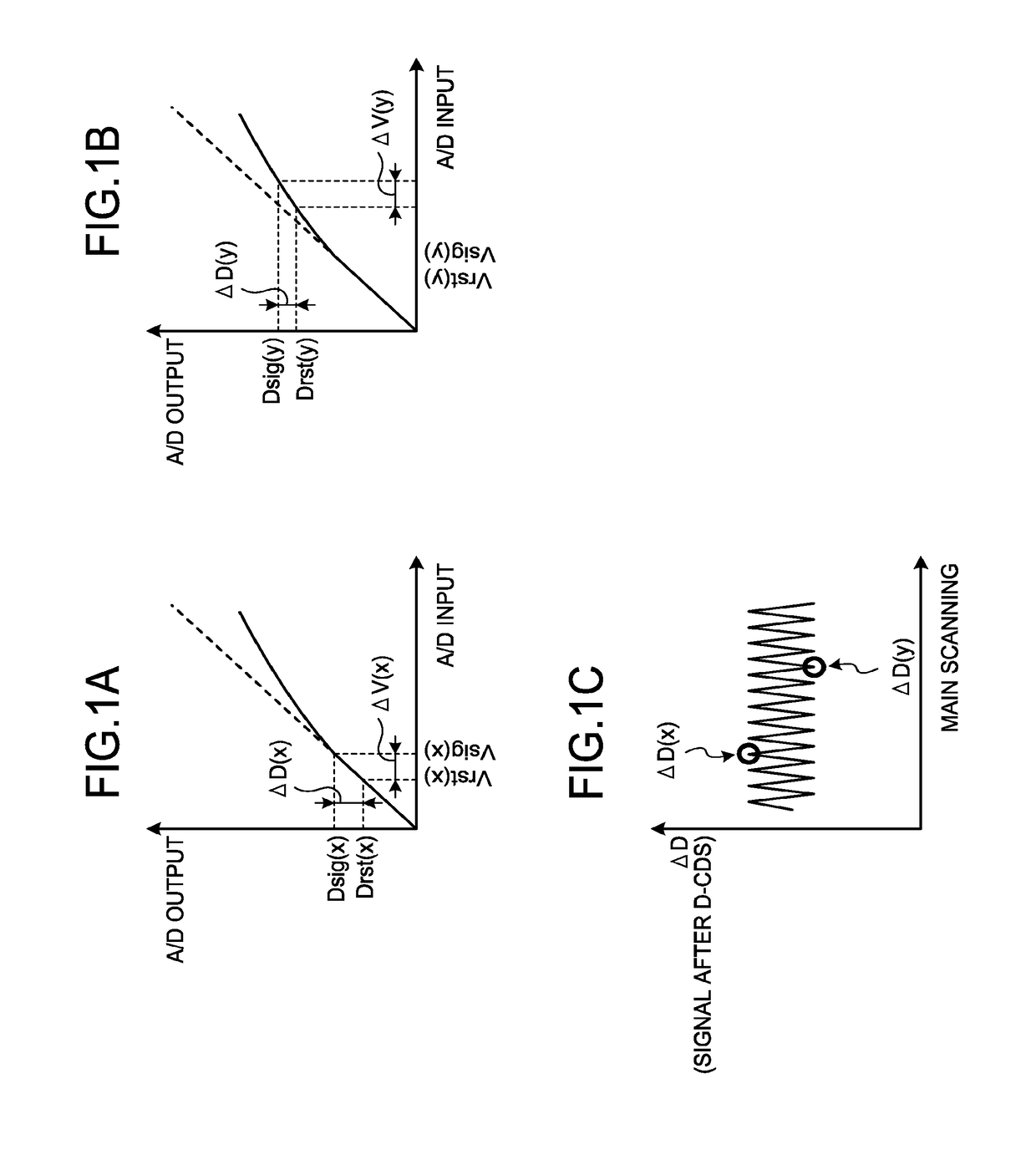
[0035]First, the background that has led to achievement of the present invention is explained. FIGS. 1A to 1C are graphs exemplifying signal ...


PUM


Abstract

A photoelectric conversion element includes: light receiving elements that convert an optical signal into an electrical signal per pixel; offset fixing units that fix an offset of an output level of each of the light receiving elements to a reference level; analog/digital conversion units that convert signals respectively corresponding to a signal level being converted from an optical signal and output by the light receiving elements and a reset level output independent of an optical signal, into digital signals, according to the reference level; amplifier units that amplify a signal; and correlated double sampling units that perform correlated double sampling per each of the light receiving elements by using a signal based on the reset level and a signal based on the signal level, wherein the amplifier units amplify the signal corresponding to the reset level and the signal corresponding to the signal level before implementing the correlated double sampling.

Description

CROSS-REFERENCE TO RELATED APPLICATIONS[0001]The present application claims priority under 35 U.S.C. §119 to Japanese Patent Application No. 2016-003734 filed Jan. 12, 2016. The contents of which are incorporated herein by reference in their entirety.BACKGROUND OF THE INVENTION[0002]1. Field of the Invention[0003]The present invention relates to a photoelectric conversion element, an image reading device, an image forming apparatus, an image reading method, and a computer-readable recording medium.[0004]2. Description of the Related Art[0005]It has been known that correlated double sampling (CDS) is performed to suppress noises in a photoelectric conversion element such as a complementary metal oxide semiconductor (CMOS) image sensor.[0006]Moreover, Japanese Unexamined Patent Application Publication No. 2006-25189 discloses an image sensor that analog / digital (A / D) converts each of a signal level and a reset level from a pixel portion by an AD converter, and stores the signal level ...

Claims


Application Information

Patent Timeline
IPC IPC(8): H04N5/357H04N5/3745H04N5/378H04N5/365
CPCH04N5/3575H04N5/378H04N5/37455H04N5/365H04N25/616H04N25/67H04N25/701H04N25/75H04N25/772
Inventor HASHIMOTO, HIDEKINAKAZAWA, MASAMOTO
Owner RICOH KK
Why Eureka
Try Eureka