
System, method, and computer program for creating geometry-compliant lattice structures

a technology of lattice structure and geometry, applied in the field of computer modeling and additive manufacturing system, can solve the problems of complex additive manufacturing process, shortened lattice structure, and inability to meet the requirements of geometry,

Active Publication Date: 2017-07-20
HONEYWELL FED MFG & TECHNOLOGI
View PDF6 Cites 4 Cited by
  • Summary
  • Abstract
  • Description
  • Claims
  • Application Information

AI Technical Summary

Benefits of technology

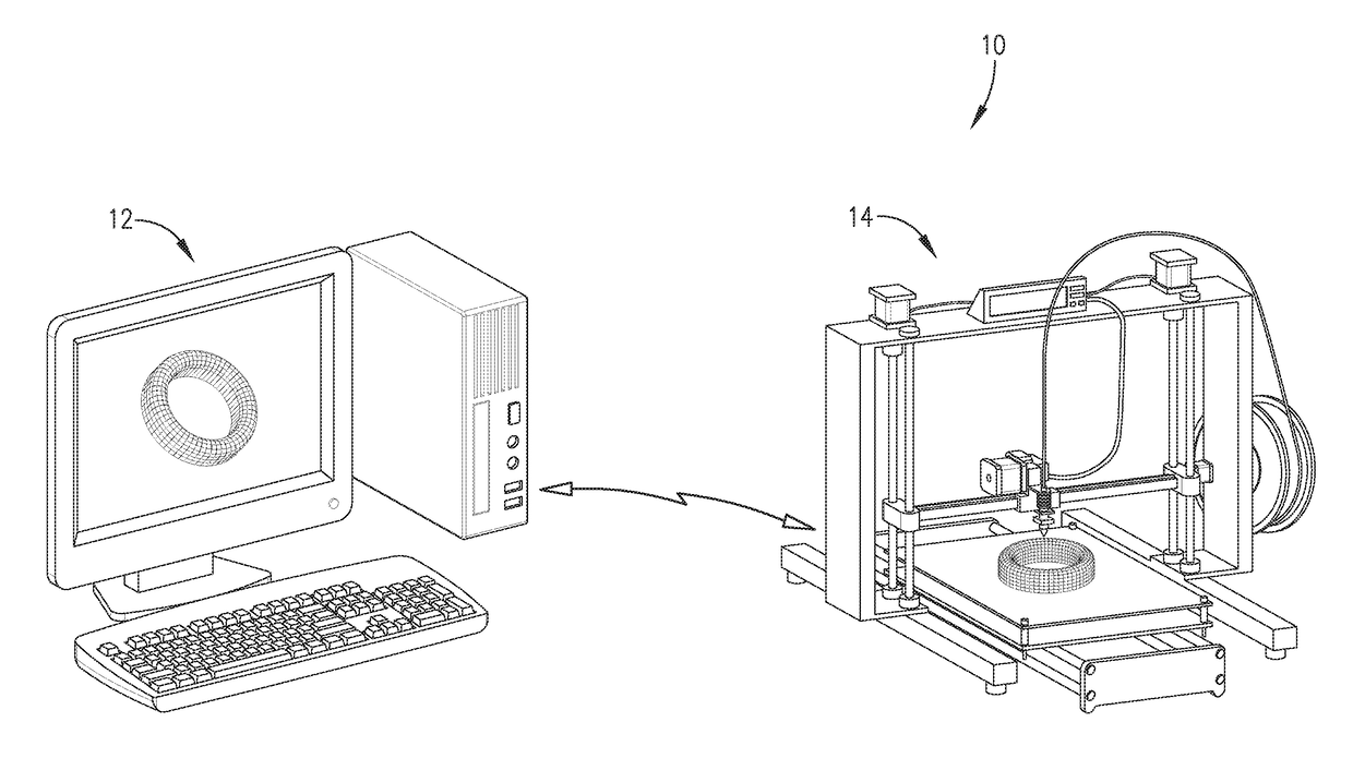
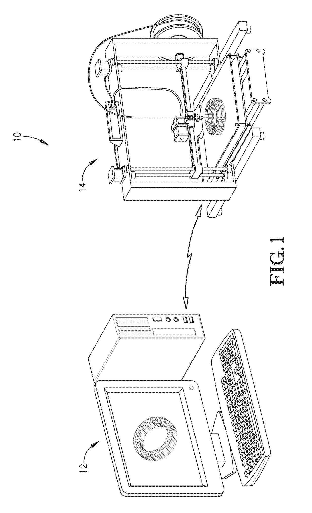
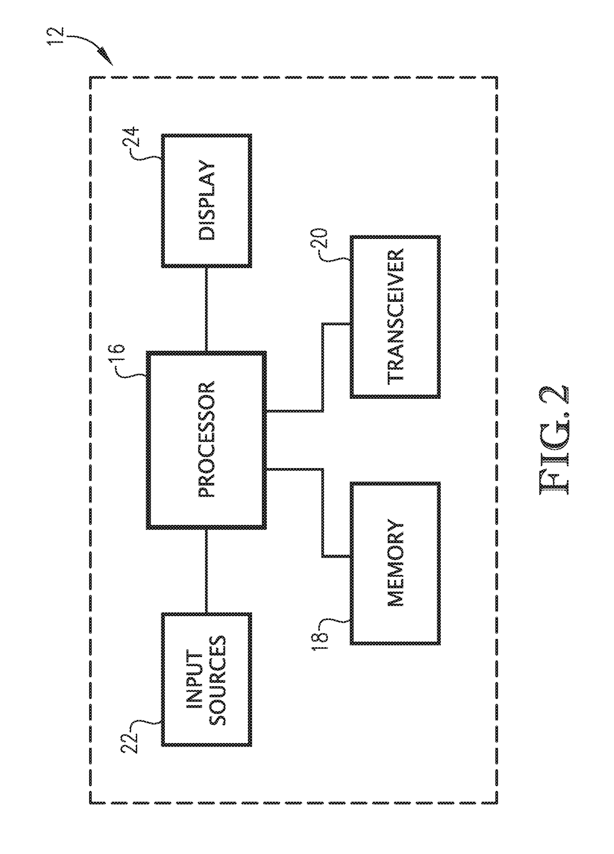
The present invention provides methods for creating a shape-conforming lattice structure by using a computer model of a part. Different embodiments of the invention involve generating a finite element mesh corresponding to the part, and then either deforming a lattice structure or free-form deforming the mesh elements to conform to the overall shape of the part. The lattice structure includes a number of cellular components that have a cellular periodicity corresponding to the mesh elements of the finite element mesh. As a result, the lattice structure preserves the overall shape of the part and receives the benefits of lattice features without introducing structural weak points or other deficiencies. The invention also enables parallel processing of the deformed lattice structure and reduces the later simulation of the entire part.

Problems solved by technology

However, these lattice structures are often truncated when overall shapes of the lattice structures do not match overall shapes of the parts.
Some of the cropped cellular components of the orthogonal lattice structure become structurally compromised as a result, which may introduce undesired stress paths and stress concentrations.
Truncating and / or cropping cellular components may also introduce unwanted artifacts in the computer model of the part, which may complicate the additive manufacturing process.

Method used


Image

  • System, method, and computer program for creating geometry-compliant lattice structures
  • System, method, and computer program for creating geometry-compliant lattice structures
  • System, method, and computer program for creating geometry-compliant lattice structures

Examples


Embodiment Construction

[0021]The following detailed description of the invention references the accompanying drawings that illustrate specific embodiments in which the invention can be practiced. The embodiments are intended to describe aspects of the invention in sufficient detail to enable those skilled in the art to practice the invention. Other embodiments can be utilized and changes can be made without departing from the scope of the present invention. The following detailed description is, therefore, not to be taken in a limiting sense. The scope of the present invention is defined only by the appended claims, along with the full scope of equivalents to which such claims are entitled.

[0022]In this description, references to “one embodiment”, “an embodiment”, or “embodiments” mean that the feature or features being referred to are included in at least one embodiment of the technology. Separate references to “one embodiment”, “an embodiment”, or “embodiments” in this description do not necessarily ref...


PUM

PropertyMeasurementUnit
lattice structureaaaaaaaaaa
lattice cellular componentaaaaaaaaaa
structural rigidityaaaaaaaaaa

Abstract

A system and method of creating a shape-conforming lattice structure for a part formed via additive manufacturing. The method includes receiving a computer model of the part and generating a finite element mesh. A lattice structure including a number of lattice cellular components may also be generated. Some of the mesh elements of the finite element mesh may be deformed so that the finite element mesh conforms to the overall shape of the part. The lattice structure may then be deformed so that the lattice structure has a cellular periodicity corresponding to the finite elements of the finite element mesh. In this way, the part retains the benefits of its overall shape and the benefits of lattice features without introducing structural weak points, directional stresses, and other structural deficiencies.

Description

BACKGROUND[0001]Additive manufacturing is often used for creating prototypes and unique, complex, and / or low-production parts. Such parts are often formed with lattice structures for improving structural rigidity without significantly increasing weight of the parts. However, these lattice structures are often truncated when overall shapes of the lattice structures do not match overall shapes of the parts. For example, an orthogonal lattice structure may be cropped to fit a part having a circular overall shape. Some of the cropped cellular components of the orthogonal lattice structure become structurally compromised as a result, which may introduce undesired stress paths and stress concentrations. Truncating and / or cropping cellular components may also introduce unwanted artifacts in the computer model of the part, which may complicate the additive manufacturing process.SUMMARY OF THE INVENTION[0002]Embodiments of the present invention solve the above-mentioned problems and provide ...

Claims


Application Information

Patent Timeline
Patent Type & Authority Applications(United States)
IPC IPC(8): B29C67/00G05B19/4099
CPCB29C67/0088G05B19/4099B33Y50/02G05B2219/49007G05B2219/35134B29C64/386Y02P90/02
Inventor VERNON, GREGORY JOHN
Owner HONEYWELL FED MFG & TECHNOLOGI
Learn More