Electrochemical cell

Active Publication Date: 2017-07-20
SEIKO INSTR INC
View PDF1 Cites 20 Cited by
  • Summary
  • Abstract
  • Description
  • Claims
  • Application Information

AI Technical Summary

Benefits of technology

[0031]According to the present invention, by drawing around the tab on the inside of the exterior body, it is possible to easily conduct the positive electrode body and the negative electrode body and other members via the tab. Therefore, it is possible to prevent struc

Problems solved by technology

However, when the negative electrode case and the positive electrode case are caulked, in some case, the negative electrode case and the positive electrode case are damaged by a caulking load acting on the cases during the caulking and airtightness on the inside of the battery is deterio

Method used


Image

  • Electrochemical cell
  • Electrochemical cell
  • Electrochemical cell

Examples


first embodiment

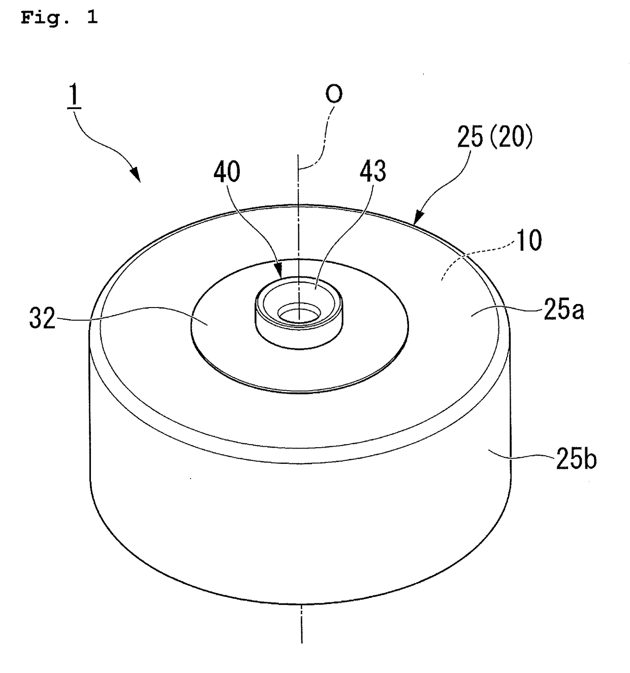
[0061]First, a battery 1 according to a first embodiment is explained.

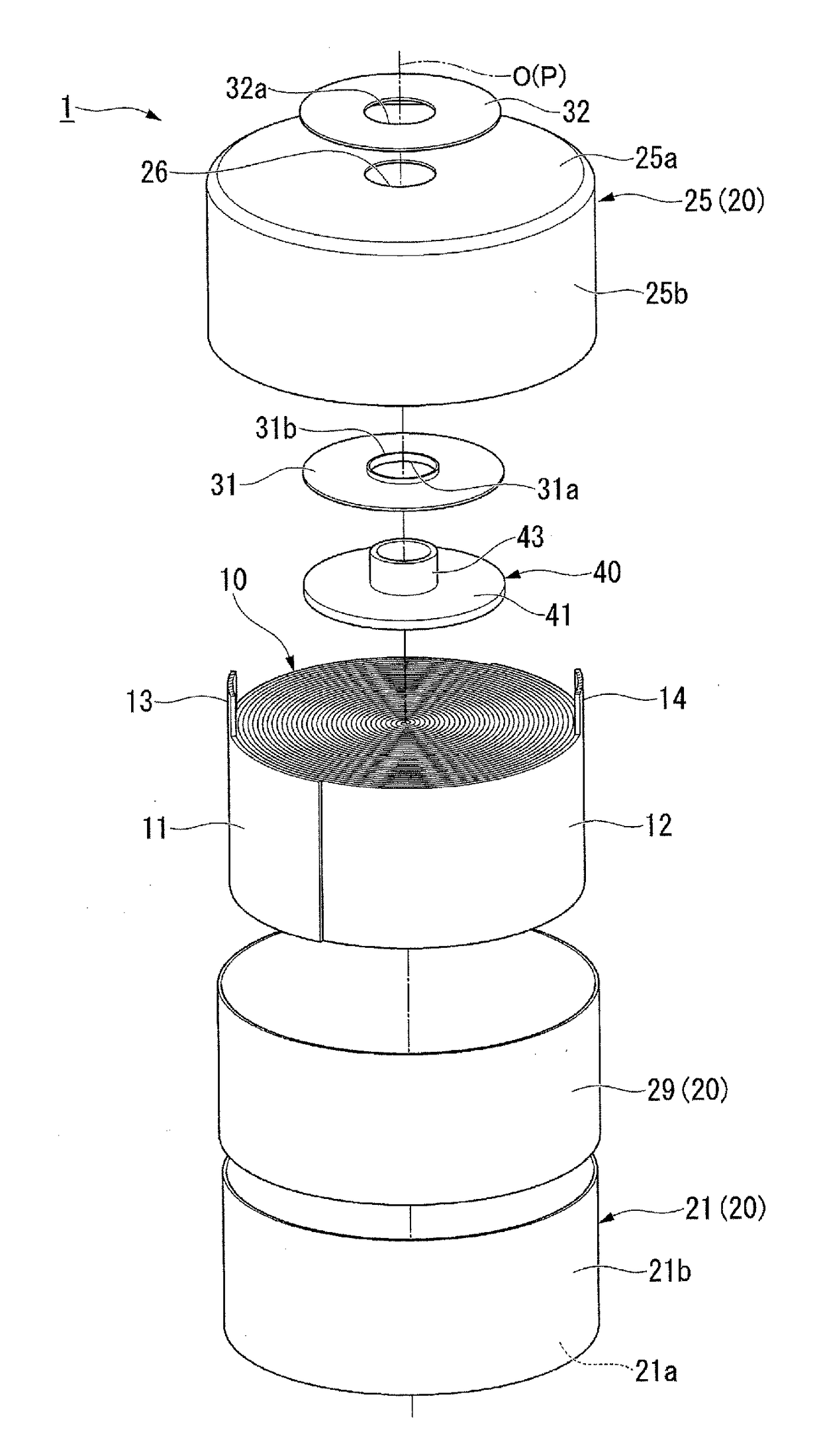
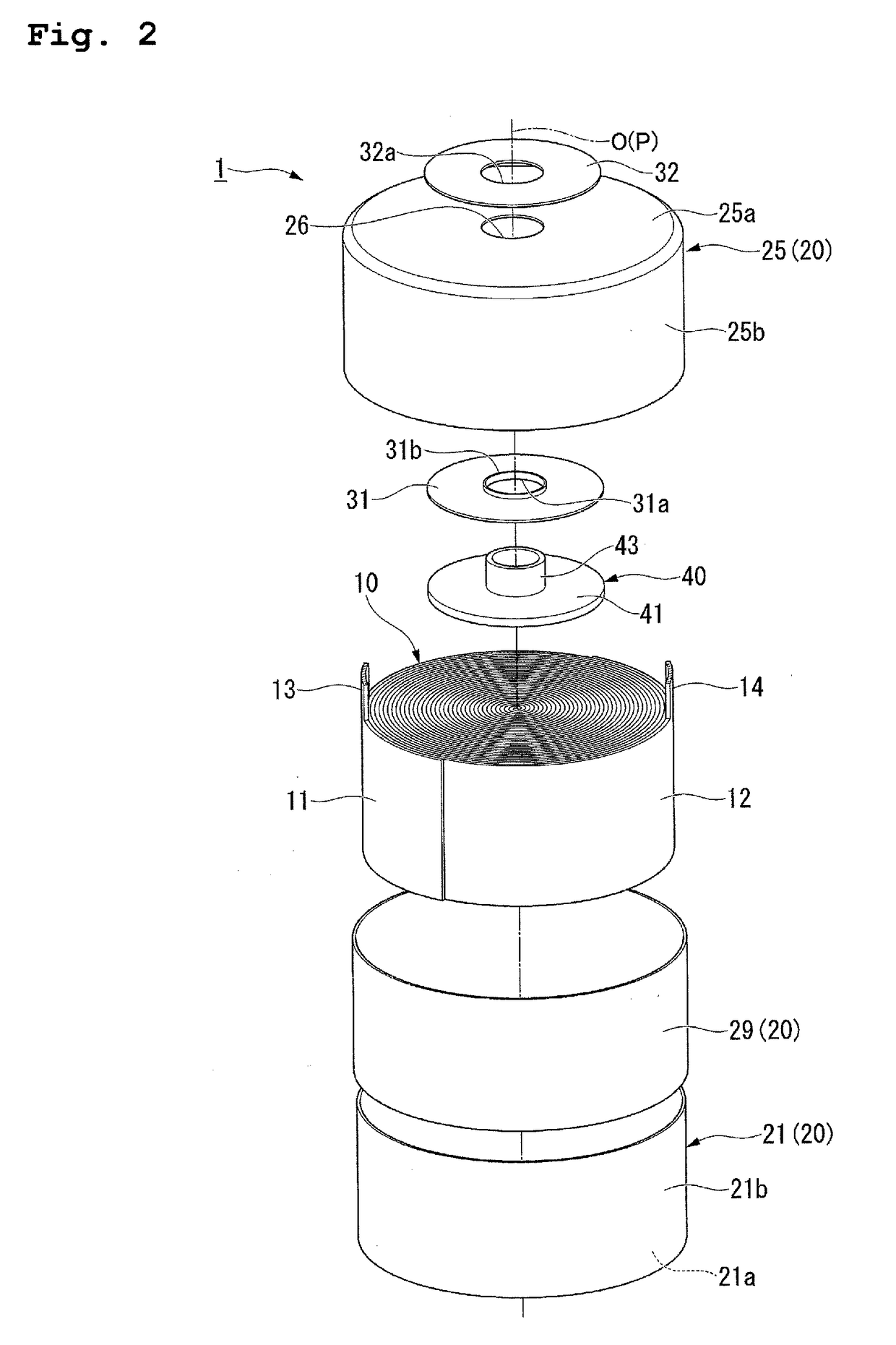
[0062]FIG. 1 is a perspective view of the battery 1 according to the first embodiment. FIG. 2 is an exploded perspective view of the battery 1 according to the first embodiment.

[0063]As shown in FIGS. 1 and 2, the battery 1 is a so-called button-type battery. The battery 1 mainly includes an electrode body 10 including a positive electrode body 11 and a negative electrode body 12 and an exterior body 20 in which the electrode body 10 is housed.

[0064]As shown in FIG. 2, the electrode body 10 is formed in a columnar shape by winding the positive electrode body 11 and the negative electrode body 12, both of which are belt-like, one on top of the other. Specifically, the electrode body 10 has structure in which the belt-like positive electrode body 11 and the belt-like negative electrode body 12 are wound around a winding axis P in a state in which the belt-like positive electrode body 11 and the belt-like negative el...

second embodiment

[0121]A battery 101 according to a second embodiment is explained.

[0122]FIG. 14 is a perspective view of the battery 101 according to the second embodiment.

[0123]In the first embodiment shown in FIGS. 1 and 2, the battery 1 is formed in a so-called button shape. The second embodiment shown in FIG. 14 is different from the first embodiment in that the battery 101 is formed in a so-called cylinder shape. Note that components same as the components in the first embodiment shown in FIGS. 1 and 2 are denoted by the same reference numerals and signs and detailed explanation of the components is omitted (the same applies to embodiments explained below).

[0124]As shown in FIG. 14, a first container 121 is formed such that a dimension in the axial direction is larger than the dimension of the second container 25. The second circumferential wall section 25b of the second container 25 surrounds an opening end portion of a first circumferential wall section 121b of the first container 121. An el...

third embodiment

[0137]A battery 201 according to a third embodiment is explained.

[0138]FIG. 22 is a perspective view of the battery 201 according to the third embodiment.

[0139]In the first embodiment shown in FIGS. 1 and 2, the battery 1 is formed in a so-called button shape. The third embodiment shown in FIG. 22 is different from the first embodiment in that the battery 201 is formed in a so-called coin shape.

[0140]FIG. 23 is an exploded perspective view of an electrode body according to the third embodiment.

[0141]As shown in FIG. 23, an electrode body 210 is configured by alternately stacking a plurality of positive electrode bodies 211 and negative electrode bodies 212 in the axial direction via not-shown separators.

[0142]The positive electrode bodies 211 are formed in a circular shape when viewed from the axial direction. The positive electrode bodies 211 include positive electrode collectors 211a made of circular metal foil and positive electrodes 211b disposed on the surfaces of the positive ...


PUM


Abstract

A battery includes an electrode body including a positive electrode body and a negative electrode body and an exterior body in which the electrode body is housed. The exterior body includes a first container formed in a bottomed cylindrical shape and including a first circumferential wall section, a second container formed in a bottomed cylindrical shape and including a second circumferential wall section surrounding the first circumferential wall section, the second container housing the electrode body between the second container and the first container, and a fusing member interposed between the first circumferential wall section and the second circumferential wall section and fused to the first circumferential wall section and the second circumferential wall section.

Description

RELATED APPLICATIONS[0001]This application claims priority under 35 U.S.C. §119 to Japanese Patent Applications No. 2016-006391 filed on Jan. 15, 2016 and No. 2016-221904 filed on Nov. 14, 2016, the entire content of which is hereby incorporated by reference.BACKGROUND OF THE INVENTION[0002]1. Field of the Invention[0003]The present invention relates to an electrochemical cell.[0004]2. Description of the Related Art[0005]As electrochemical cells such as a nonaqueous electrolyte secondary battery and an electrical double layer capacitor, there are electrochemical cells formed in button shapes (in the following explanation, including a coin shape and a cylinder shape). The button-type electrochemical cells are used in, for example, power supplies of various devices. As one form of the button-type electrochemical cells, for example, a battery disclosed in JP-A-2002-298803 (Patent Literature 1) described below is proposed.[0006]Patent Literature 1 discloses a configuration in which a ne...

Claims


Application Information

Patent Timeline
IPC IPC(8): H01M10/0587H01G11/74H01M2/26H01G11/78H01M2/06H01M2/02H01M50/119H01M50/121H01M50/124H01M50/548H01M50/559
CPCH01M10/0587H01M2/06H01G11/74H01M2/263H01G11/78H01M2/0292H01G11/82H01G11/16Y02E60/10H01M50/107H01M50/124Y02P70/50H01M50/559H01M50/121H01M50/548H01M50/119
Inventor TAMACHI, TSUNEAKIWATANABE, SHUNJI
Owner SEIKO INSTR INC
Why Eureka
Try Eureka