Antenna system employing a rotatable circularly polarized antenna feed

a circularly polarized, antenna feed technology, applied in the direction of antennas, electrical equipment, etc., can solve the problems of loss, difficult rotation of antenna dishes, and inability to perfectly align antenna feeds at gateways and orbiting satellites, so as to reduce cross-pol discrimination

Active Publication Date: 2017-07-20
HUGHES NETWORK SYST
View PDF3 Cites 6 Cited by
  • Summary
  • Abstract
  • Description
  • Claims
  • Application Information

AI Technical Summary

Benefits of technology

[0007]In view of these drawbacks of the state of the known technology, one aspect of the present invention provides a gateway antenna dish arrangement in which the antenna feed is rotatably coupled to the antenna dish so that the antenna feed can be rotated without rotating the entire antenna dish. Thus, an embodiment of the present invention provides an antenna system that comprises an antenna feed support and a driver. The antenna feed support is configured to mount a circularly polarized antenna feed to an antenna dish to extend outward along a longitudinal axis of the circularly polarized antenna feed with respect to a reflective surface of the antenna dish. The driver is configured to rotate the circularly polarized antenna feed to adjust alignment between the circularly polarized antenna feed and a remote antenna. The driver can rotate the circularly polarized antenna feed mechanically, electrically or both to adjust alignment between the circularly polarized antenna feed and a remote antenna to reduce cross-pol discrimination (XPD) at the circularly polarized antenna feed.

Problems solved by technology

However, since the polarization of these antenna feeds at the gateway and the orbiting satellite are not perfectly circular and have some elliptical characteristics, the antenna feeds at the gateway and the orbiting satellite often will not be perfectly aligned with each other.
This misalignment causes some loss to be present in the communication link between the gateway and orbiting satellite.
However, because an antenna dish at the gateway is typically 5 to 8 meters in diameter, these types of antenna dishes are generally difficult to rotate.

Method used


Image

  • Antenna system employing a rotatable circularly polarized antenna feed
  • Antenna system employing a rotatable circularly polarized antenna feed
  • Antenna system employing a rotatable circularly polarized antenna feed

Examples


Embodiment Construction

[0016]Selected embodiments will now be explained with reference to the drawings. It will be apparent to those skilled in the art from this disclosure that the following descriptions of the embodiments are provided for illustration only and not for the purpose of limiting the invention as defined by the appended claims and their equivalents.

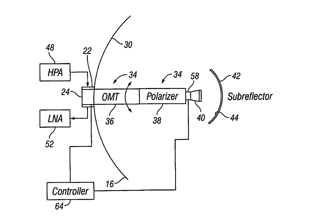
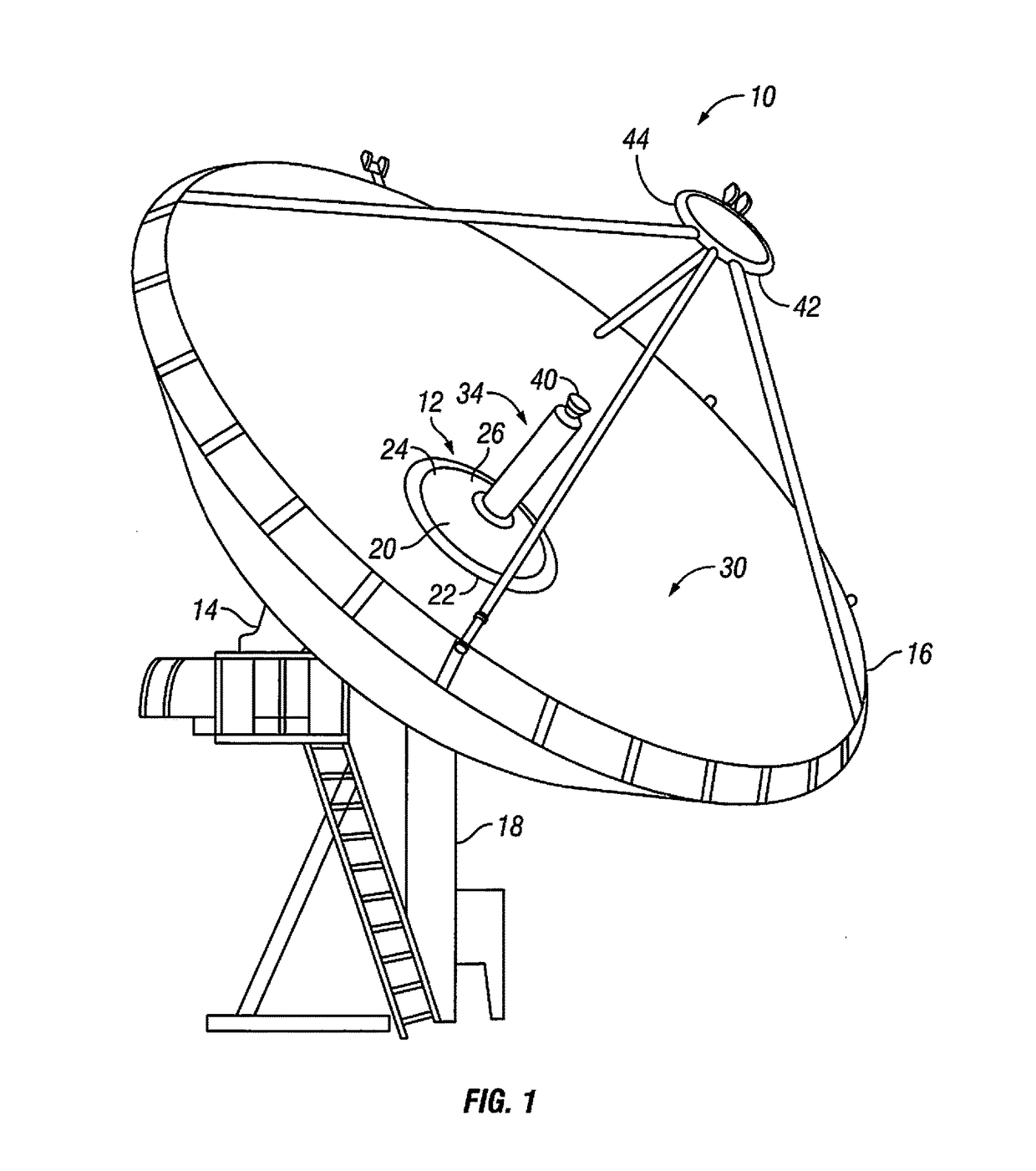
[0017]FIG. 1 illustrates an example of a gateway antenna 10 for use in a satellite communication network. The gateway antenna 10 is installed terrestrially at a desired location on the Earth, and includes an antenna system 12 and a gateway antenna equipment room 14. In this example, the antenna system 12 includes an antenna dish 16 that is pivotally mounted to a terrestrially mounted antenna dish base 18 in any conventional manner as understood in the art. Thus, the antenna dish 16 can be manually or automatically pointed in azimuth and elevation to align the antenna dish 16 with an antenna dish of an orbiting satellite (not shown) in any conventi...


PUM


Abstract

An antenna system comprises an antenna feed support and a driver. The antenna feed support is configured to mount a circularly polarized antenna feed to an antenna dish to extend outward along a longitudinal axis of the circularly polarized antenna feed with respect to a reflective surface of the antenna dish. The driver is configured to rotate the circularly polarized antenna feed to adjust alignment between the circularly polarized antenna feed and a remote antenna. The driver can rotate the circularly polarized antenna feed mechanically, electrically or both to adjust alignment between the circularly polarized antenna feed and a remote antenna to reduce cross-pol discrimination at the circularly polarized antenna feed.

Description

BACKGROUND[0001]Field of the Invention[0002]The present invention generally relates to an antenna system and method for installing an antenna system. More particularly, the present invention relates to an antenna system employing a rotatable antenna feed, in particular, a rotatable circularly polarized antenna feed, and a method for installing and operating such an antenna system.[0003]Background Information[0004]As understood in the art, satellite communication systems include a plurality of terrestrially mounted gateways that communicate with one or more orbiting satellites. Each satellite gateway includes an antenna dish, an antenna feed and other types of equipment such a transceiver, amplifiers, waveguides and so on which enable communication between the satellite gateway and one or more of the orbiting satellites. The satellite gateway and a satellite typically communicate with each other over a radio frequency link, such as a Ku-band link, a Ka-band link or any other suitable...

Claims


Application Information

Patent Timeline
Patent Type & Authority Applications(United States)
IPC IPC(8): H01Q3/18H01Q15/24H01Q15/16
CPCH01Q3/18H01Q15/24H01Q15/16H01Q19/13H01Q19/19
Inventor LUNDSTEDT, JACKHOU, PETERFARROW, DAVIDKOLLIPARA, RAMESH
Owner HUGHES NETWORK SYST
Why Eureka
Try Eureka