Optical Disc Apparatus and Method for Discriminating Optical Disc

a technology of optical discs and apparatuses, applied in the field of optical discs, can solve the problems of discs not having wobble, deteriorating the s/n ratio of wobble signals to be detected, and increasing internal noise of circuits, so as to minimize the delay in the setup process, reduce disc discrimination errors, and improve the accuracy of wobble signals

Inactive Publication Date: 2009-08-13
HITACHI-LG DATA STORAGE
View PDF2 Cites 0 Cited by
  • Summary
  • Abstract
  • Description
  • Claims
  • Application Information

AI Technical Summary

Benefits of technology

[0014]According to the present invention, wobble signal detection accuracy can be improved and disc discrimination errors reduced. This minimizes a delay in setup process.

Problems solved by technology

Simplifying the signal-processing circuit in an attempt to reduce apparatus costs, however, increases the internal noise of the circuit, thus deteriorating the S / N ratio of the wobble signal to be detected.
As a result, a disc not having the wobble (e.g., a DVD-ROM disc) will be erroneously discriminated as a disc having the wobble (e.g., a DVD-RW disc).
The occurrence of this discrimination error will make it absolutely necessary to restart the discrimination itself by use of a different technique, resulting in a delay in setup process.
The technique described in JP-A-2006-179138 is intended to discriminate the kind of disc from the frequency distribution of the wobble signal, but does not avoid the above influence of the noise.

Method used


Image

  • Optical Disc Apparatus and Method for Discriminating Optical Disc
  • Optical Disc Apparatus and Method for Discriminating Optical Disc
  • Optical Disc Apparatus and Method for Discriminating Optical Disc

Examples


first embodiment

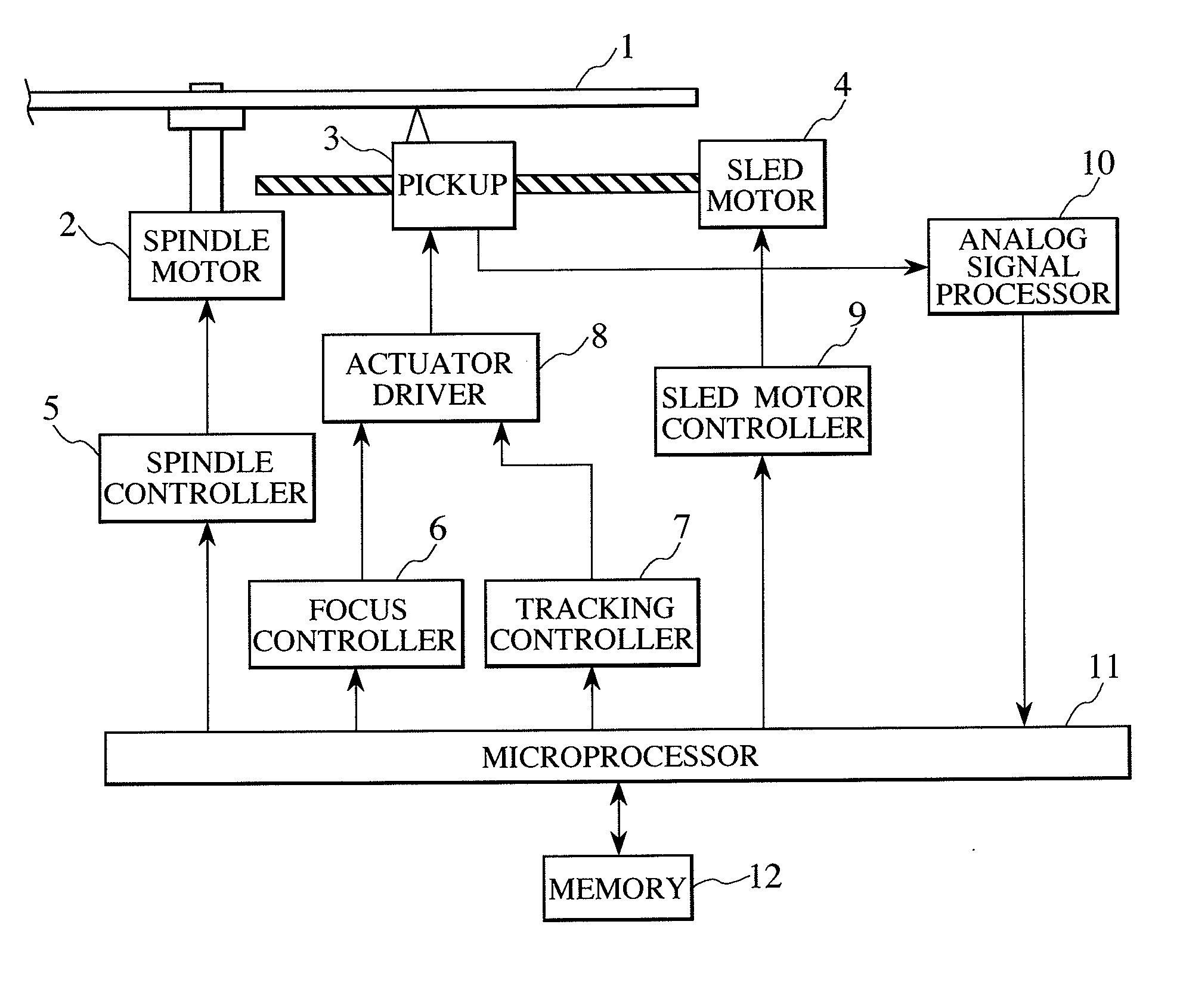
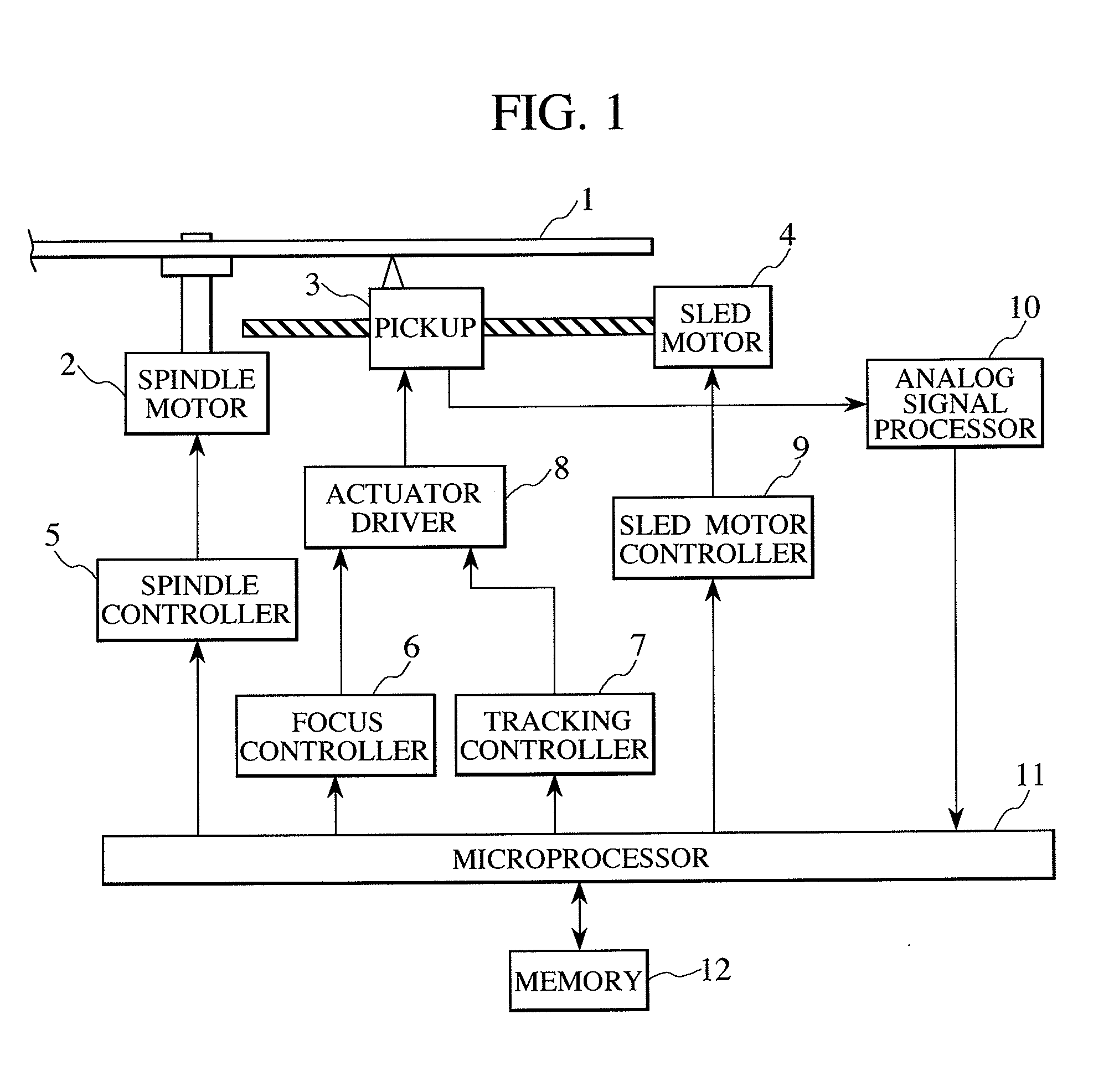
[0022]FIG. 1 is a block diagram showing an optical disc apparatus of the present invention.

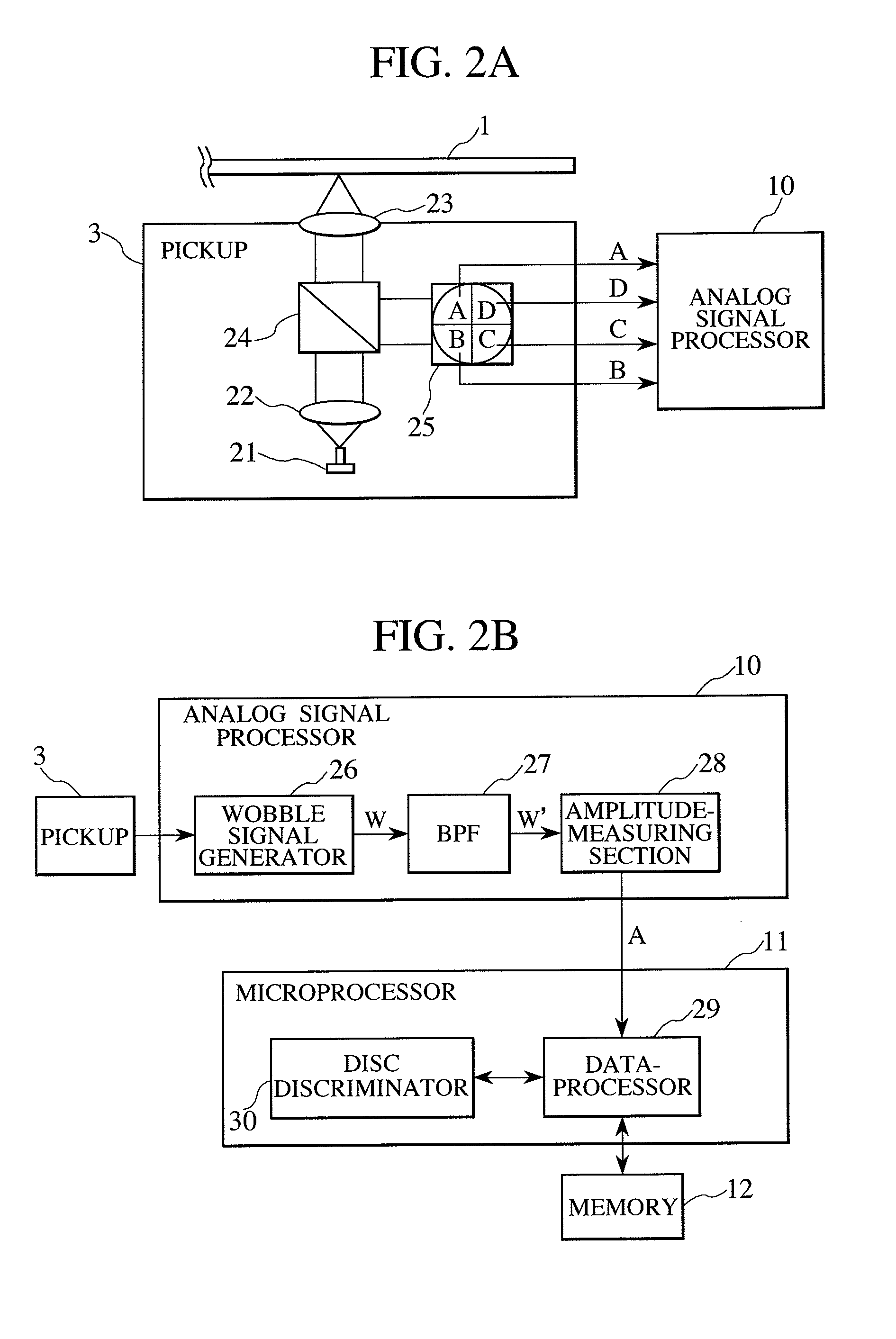
[0023]The optical disc apparatus rotates an optical disc 1 using a spindle motor 2, then irradiates the optical disc 1 with laser light from a pickup 3, and reads out data using the resulting return light. Also, moving the pickup 3 in a radial direction by means of a sled motor changes a location of the data to be read out. The return light that has been input to the pickup 3 is converted into electrical signals, which are then sent to an analog signal processor 10 to reproduce the data (information) and to generate a tracking error (TE) signal, a focus error (FE) signal, and more. A microprocessor 11 calculates control quantities for the spindle motor 2, the pickup 2, and the sled motor 4, from these signals and sends control signals to a spindle controller 5, a focus controller 6, a tracking controller 7, and a sled motor controller 9. After receiving the associated control signal, each of t...

second embodiment

[0034]FIG. 4 is a flowchart showing a second embodiment that is an example of a disc discrimination method based on the present invention. This example uses an N number of BPFs in addition to standard BPF data setting.

[0035]In step S200, a mounted disc is rotated and after optical beam irradiation, the resulting return light signals are input to start disc discrimination.

[0036]In step S201, the central frequency “f” of the BPF 27 is set to equal the wobble frequency f0 (standard setting).

[0037]In step S202, amplitude A0 of a filtered signal is measured by the amplitude-measuring section 28 and the measured value is saved in the memory 12.

[0038]In step S203, n=1 is assigned as a counter value.

[0039]In step S204, the central frequency “f” of the BPF 27 is changed to fn (initially, n=1) that is different from the wobble frequency f0. For example, the central frequency is set at equal intervals in accordance with fn=(n+1)×f0. Needless to say, the central frequency may be set at unequal ...

third embodiment

[0046]FIG. 5 is a flowchart showing a third embodiment that is yet another example of a disc discrimination method. This example uses the number of BPFs that is associated with N=1 in FIG. 4.

[0047]In step S300, a mounted disc is rotated and after optical beam irradiation, the resulting return light signals are input to start disc discrimination.

[0048]In step S301, the central frequency “f” of the BPFs is set to equal the wobble frequency f0 (standard setting).

[0049]In step S302, amplitude A0 of a filtered signal is measured and the measured value is saved in the memory.

[0050]In step S303, the central frequency “f” of the BPFs is changed to f1 different from the wobble frequency f0. For example, “f” is changed so that f1=2×f0.

[0051]In step S304, amplitude Al of another filtered signal is measured and the measured value is stored in the memory.

[0052]In step S305, the amplitude levels A0 and A1 are read out from the memory for comparison. If the two values differ by the threshold level...


PUM

PropertyMeasurementUnit
wobble frequency f0aaaaaaaaaa
frequencyaaaaaaaaaa

Abstract

This invention improves the accuracy of wobble signal detection for disc discrimination and reduces discrimination errors due to noise. In an optical disc apparatus, a wobble signal generator creates a wobble signal from an electrical signal which has been obtained from conversion by a pickup. A bandpass filter (BPF) is set to change its central frequency to a wobble frequency f0 and to fn different from the wobble frequency, and the filter extracts the respective frequency components from the wobble signal. An amplitude-measuring section measures amplitude levels A0 and An of the extracted multiple signals. A disc discriminator compares the multiple amplitude levels and if the amplitude A0 is greater than the amplitude An by at least a threshold level Ath, judges that a wobble is present.

Description

CLAIM OF PRIORITY[0001]The present application claims priority from Japanese patent application JP 2008-031698 filed on Feb. 13, 2008, the content of which is hereby incorporated by reference into this application.BACKGROUND OF THE INVENTION[0002](1) Field of the Invention[0003]The present invention relates to an optical disc apparatus capable of discriminating the kind of optical disc by detecting a wobble signal and a method for discriminating an optical disc.[0004](2) Description of the Related Art[0005]Optical disc apparatuses discriminate the kind of mounted optical disc by a combination of factors such as the depth of the recording layer, the reflectance of the disc, the presence / absence of a wobble signal, and the settings of control data. Whether the disc is intended for recording or for reproduction only, however, can be discriminated from the presence / absence of a wobble signal, not from the above combination. That is to say, whereas DVD-R / RW and DVD+R / RW discs, both for r...

Claims


Application Information

Patent Timeline
Patent Type & Authority Applications(United States)
IPC IPC(8): G11B7/00
CPCG11B19/12
Inventor TANAKA, HIDEAKIINABA, SEIJISAKAI, HIROHARU
Owner HITACHI-LG DATA STORAGE
Why Eureka
Try Eureka