Linerless label imaging and cutting

Inactive Publication Date: 2017-07-27
DATALASE
View PDF1 Cites 2 Cited by
  • Summary
  • Abstract
  • Description
  • Claims
  • Application Information

AI Technical Summary

Benefits of technology

This patent is about a machine that can make and cut labels without using a liner. The label has a special layer that changes color when it is printed on. The machine uses a laser to create the image and cut the label as it moves through the machine. The machine can use different types of release layers, such as silicone, wax, or other substances. These layers can be applied without a solvent and can be transparent or absorb laser radiation. The release layer can help with image formation if it has some absorption to the laser.

Problems solved by technology

The above techniques all have the disadvantages the backing liner is waste and needs to be disposed of or recycled.
Additionally, the backing liner adds thickness, which limits the number of labels that can be provided on a reel for use in a labelling apparatus.
Furthermore, use of pre-cut labels requires an additional level of complexity in manufacturing since the labels must be cut after formation on the backing liner.
Whilst this does allow the elimination of the release layer it adds more complexity to the application process.
Furthermore, this activation generally results in slower application of labels and a consequently reduced product throughput.
This has the disadvantage that the blade wears over extended use and must be replaced.
Additionally, the blade accumulates debris and adhesive during use and thus requires regular cleaning.
With this approach, it is not possible to adjust the length of label at the point of application even if the size of the imaged region can be modified by the printing or imaging system.
Moreover, variation in tension applied to the label substrate (or indeed variations in the perforations) can cause premature tearing of the perforations, particularly when the strip of label substrate is rewound during the manufacturing process.
Therefore any benefit of removing a liner from the label with regard to increasing in the interval to reload the machine is lost.
The provision of registration marks requires additional manufacturing steps ahead of printing increasing the complexity and cost of label manufacture.

Method used


Image

  • Linerless label imaging and cutting
  • Linerless label imaging and cutting

Examples


Embodiment Construction

[0034]In order that the invention may be more clearly understood an embodiment thereof will now be described, by way of example only, with reference to the accompanying drawings, of which:

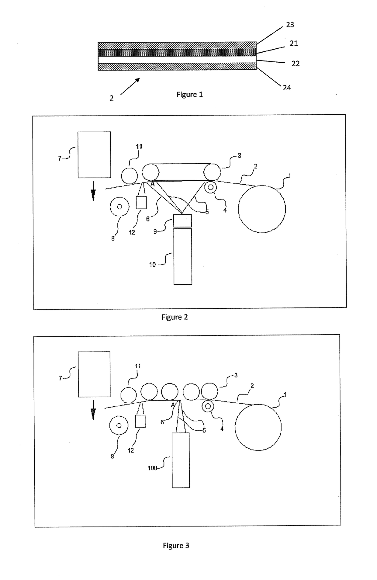
[0035]FIG. 1 is a schematic illustration of a linerless label substrate for use in the present invention;

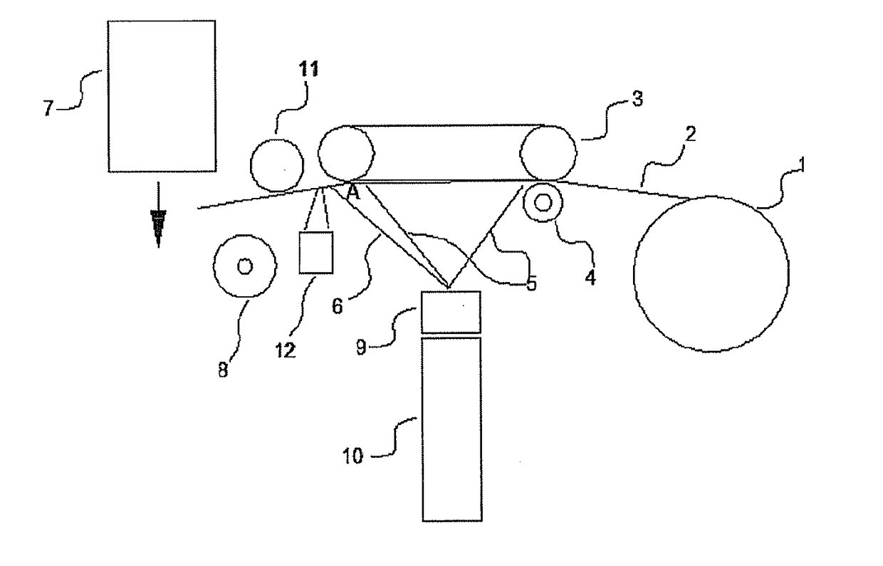
[0036]FIG. 2 is a schematic illustration of a label printing and cutting apparatus for a linerless label substrate according to the present invention; and

[0037]FIG. 32 is a schematic illustration of an alternative embodiment of a label printing and cutting apparatus for a linerless label substrate according to the present invention.

[0038]The present invention discloses a method and apparatus for imaging, cutting and applying a label to a package or product. In particular the present invention discloses a method and apparatus for imaging, cutting and applying a linerless label substrate 2 as shown in FIG. 1. The label substrate 2 comprises a base layer 21, a colour change layer 22, an adhesive la...


PUM


Abstract

A method and apparatus for imaging, cutting and applying a linerless label substrate 2. The substrate 2 is transported to an imaging area and is selectively illuminated by a suitable laser to form an image. By determining the position of the edge of the image, further laser illumination is used to cut the label substrate thereby providing a single label for application to an object. In this manner, the method of the present invention provides all the benefits of a linerless labelling system plus enables flexibility in printing labels of different sizes.

Description

TECHNICAL FIELD OF THE INVENTION[0001]The present invention relates to a label printing and cutting, in particular to a method and apparatus for printing and cutting linerless labels. Most particularly, the method and apparatus are provided with one or more lasers operable to generate images in or on the label using a colour change technology and one or more lasers operable to cut or perforate the label.BACKGROUND TO THE INVENTION[0002]Inkless printing of labels is an alternative to traditional label printing techniques such as inkjet or thermal transfer where a pigment is applied to a label substrate. The inkless method utilises a substrate whose physical properties (in particular its colour) can be altered upon irradiation with patterns of radiation.[0003]Label application methods and apparatus are well known in the packaging industry. Typically, many label application methods operate using pre-cut labels supported on a backing liner. Each label may be printed with an identical de...

Claims


Application Information

Patent Timeline
IPC IPC(8): B41J11/70B41J3/407
CPCB41J3/4075B41J11/70B41J2/455B41J11/703B65C9/1803B65C9/46B65C11/0284B65C2009/1846B26D5/00B41J11/663B65C9/00
Inventor WYRES, CHRISPHILLIPS, TRISTAN
Owner DATALASE
Why Eureka
Try Eureka