Label imaging and cutting

a label and label technology, applied in labelling, duplicating/marking methods, labelling, etc., can solve the problems of reducing the number of labels that can be provided on a reel, and requiring an additional level of manufacturing complexity, so as to reduce the level of laser radiation absorption and facilitate image formation

Active Publication Date: 2017-09-28
DATALASE
View PDF6 Cites 3 Cited by
  • Summary
  • Abstract
  • Description
  • Claims
  • Application Information

AI Technical Summary

Benefits of technology

[0036]The release layer may be: silicone based; non-silicone based; or a mixture thereof. Suitable silicone based release layers include, but are not limited to: vinyl silicones. Examples of silicone release agents include the Syl-Off® range supplied by Dow Corning. Suitable non-silicone release layers include, but are not limited to: waxes and non-waxes, polyethylene, ethoxylated alcohols, alkyd polymers, polyvinyl alkyl carbamates. The release layer may be: solventless, solvent-based, emulsion, heat-curable or UV-curable. The release layer may be transparent to laser radiation or may have a small level of laser radiation absorption. If the release layer does have a small level of laser absorption, this can assist in image formation.

Problems solved by technology

The above techniques all have the disadvantages the backing liner is waste and needs to be disposed of or recycled.
Additionally, the backing liner adds thickness, which limits the number of labels that can be provided on a reel for use in a labelling apparatus.
Furthermore, use of pre-cut labels requires an additional level of complexity in manufacturing since the labels must be cut after formation on the backing liner.
This has the disadvantage that the blade wears over extended use and must be replaced.
Additionally, the blade accumulates debris and adhesive during use and thus requires regular cleaning.
With this approach, it is not possible to adjust the length of label at the point of application even if the size of the imaged region can be modified by the printing or imaging system.
Moreover, variation in tension applied to the label substrate (or indeed variations in the perforations) can cause premature tearing of the perforations, particularly when the strip of label substrate is rewound during the manufacturing process.
Therefore any benefit of removing a liner from the label with regard to increasing in the interval to reload the machine is lost.
One of the problems with using the same laser illumination means for marking and cutting is that the spot size optimised for marking is not optimum for cutting.
The larger spot size required for marking means that when the laser needs to cut the time required for this operation is longer, increasing costs.
Additionally, the kerf cut width is wider than is desirable, potentially increasing the impact on the fume extraction system and thereby limiting filter lifetime in said extraction system.
Requiring multiple scans limits the maximum imaging rate of the label.

Method used


Image

  • Label imaging and cutting
  • Label imaging and cutting
  • Label imaging and cutting

Examples


first embodiment

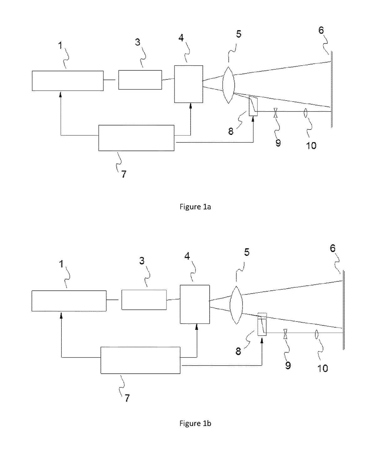
[0038]FIG. 1a is a schematic illustration of an apparatus for imaging and cutting a label according to the present invention;

[0039]FIG. 1b is a schematic illustration of a variant of the first embodiment of an apparatus for imaging and cutting a label according to the present invention;

second embodiment

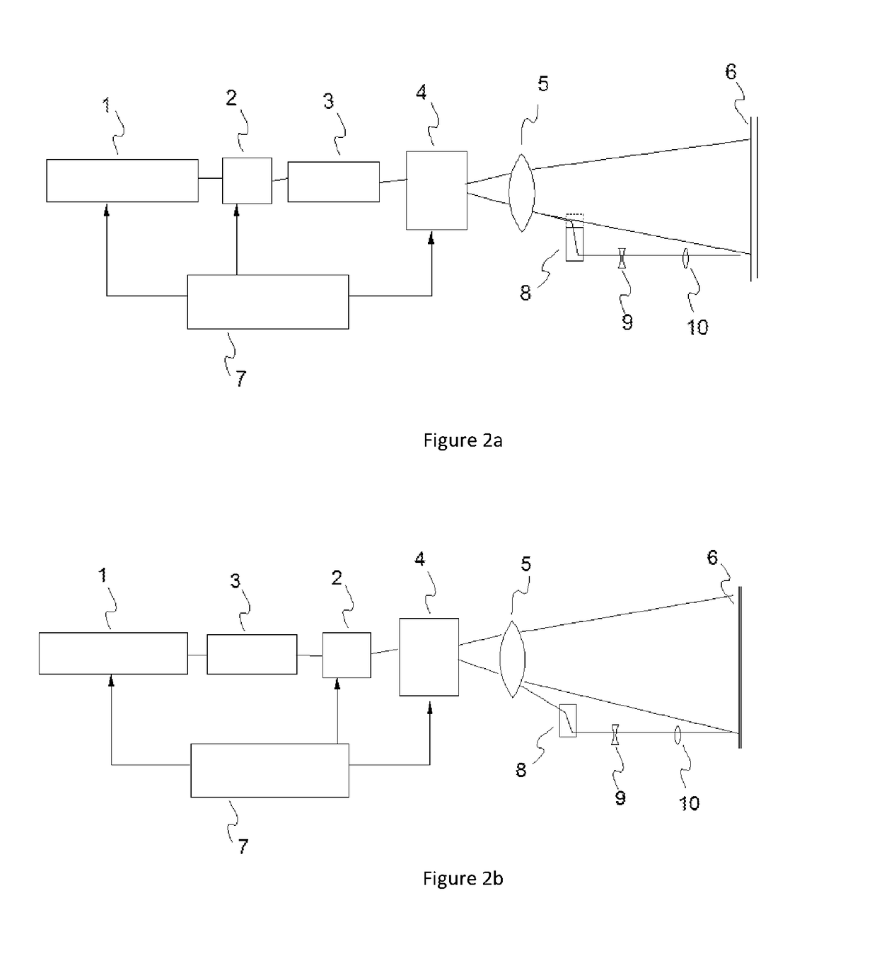
[0040]FIG. 2a is a schematic illustration of an apparatus for imaging and cutting a label according to the present invention;

[0041]FIG. 2b is a schematic illustration of a variant of the second embodiment of an apparatus for imaging and cutting a label according to the present invention;

third embodiment

[0042]FIG. 3a is a schematic illustration of an apparatus for imaging and cutting a label according to the present invention;

[0043]FIG. 3b is a schematic illustration of a variant of the third embodiment of an apparatus for imaging and cutting a label according to the present invention;

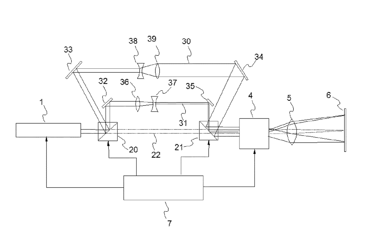
[0044]FIG. 4 is a schematic illustration of a variant of the third embodiment of an apparatus for imaging and cutting a label according to the present invention, including a schematic illustration of the optical elements of a variable beam expander; and


PUM

PropertyMeasurementUnit
operating wavelengthaaaaaaaaaa
scan speedaaaaaaaaaa

Abstract

The present invention discloses a method and apparatus for imaging and cutting a label from a linerless label substrate 6, the substrate 6 comprising: a paper or polymeric film base layer; a colour change layer, incorporating a colour change compound operable to change colour in response to illumination by a laser 1; an adhesive layer; and a release layer adapted to have low adherence to the adhesive layer. The label substrate 6 is transported from a storage reel to an imaging area. At the imaging area, the label substrate 6 is selectively illuminated by laser 1 to form an image in the colour change layer. Subsequently, further laser illumination is used to cut the label substrate 6 thereby providing a single label for application to an object. The invention is characterised in that the laser spot size is varied for imaging and cutting.

Description

TECHNICAL FIELD OF THE INVENTION[0001]The present invention relates to a label printing and cutting, in particular to a method and apparatus for printing and cutting linerless labels. Most particularly, the method and apparatus are provided with one or more lasers operable both to generate images in or on the label using a colour change technology and to cut or perforate the label.BACKGROUND TO THE INVENTION[0002]Inkless printing of labels is an alternative to traditional label printing techniques such as inkjet or thermal transfer where a pigment is applied to a label substrate. The inkless method utilises a substrate whose physical properties (in particular its colour) can be altered upon irradiation with patterns of radiation.[0003]Label application methods and apparatus are well known in the packaging industry. Typically, many label application methods operate using pre-cut labels supported on a backing liner. Each label may be printed with an identical design or may have region...

Claims


Application Information

Patent Timeline
Patent Type & Authority Applications(United States)
IPC IPC(8): B65C9/18B41J3/407B41M5/30B41J11/66
CPCB65C9/1803B41M5/30B41J3/4075B41J11/663B23K26/38B41J11/703B41M5/32B41M5/323B41M5/333B65C9/46B65C2009/1846B23K2103/40B65C9/00B41J2/442B41J2/4753
Inventor CRIDLAND, JOHN
Owner DATALASE
Why Eureka
Try Eureka