Method and system for optical measurement via a resonator having a non-uniform phase profile

a phase profile and optical measurement technology, applied in the field of optical measurement systems, can solve the problems of limiting the resolution of the optical measurement system, diffraction limitations, and inability to solve small features with typical far-field techniques, and achieve the effect of reducing spot size and improving resolution

Inactive Publication Date: 2007-03-20
XYRATEX CORP
View PDF5 Cites 11 Cited by
  • Summary
  • Abstract
  • Description
  • Claims
  • Application Information

AI Technical Summary

Benefits of technology

[0011]A scanning system may be employed to move the first surface across a surface of interest that forms the second surface of the resonator, providing a scanning surface measurement system having enhanced resolution, either due to the reduced spot size or via an interaction of a phase discontinuity with surface features of the surface of interest. The surface features may be surface features of a surface under measurement or may be data-bearing features of an optical storage medium such as optical disc media.

Problems solved by technology

Resolving small features is not possible with typical far-field techniques, due to the interaction of the feature edges that each produce a diffracted beam.
The diffracted field expands in a manner inversely proportional with the size of the structures and the diffracted beams from each of the features then interfere during the field propagation.
The contribution from each of the discrete edges cannot be separated, causing the “diffraction limitations” well known in optical systems.
However, even with resonator enhancement, diffraction still places a limitation on the resolution of an optical measurement system.

Method used


Image

  • Method and system for optical measurement via a resonator having a non-uniform phase profile
  • Method and system for optical measurement via a resonator having a non-uniform phase profile
  • Method and system for optical measurement via a resonator having a non-uniform phase profile

Examples


Embodiment Construction

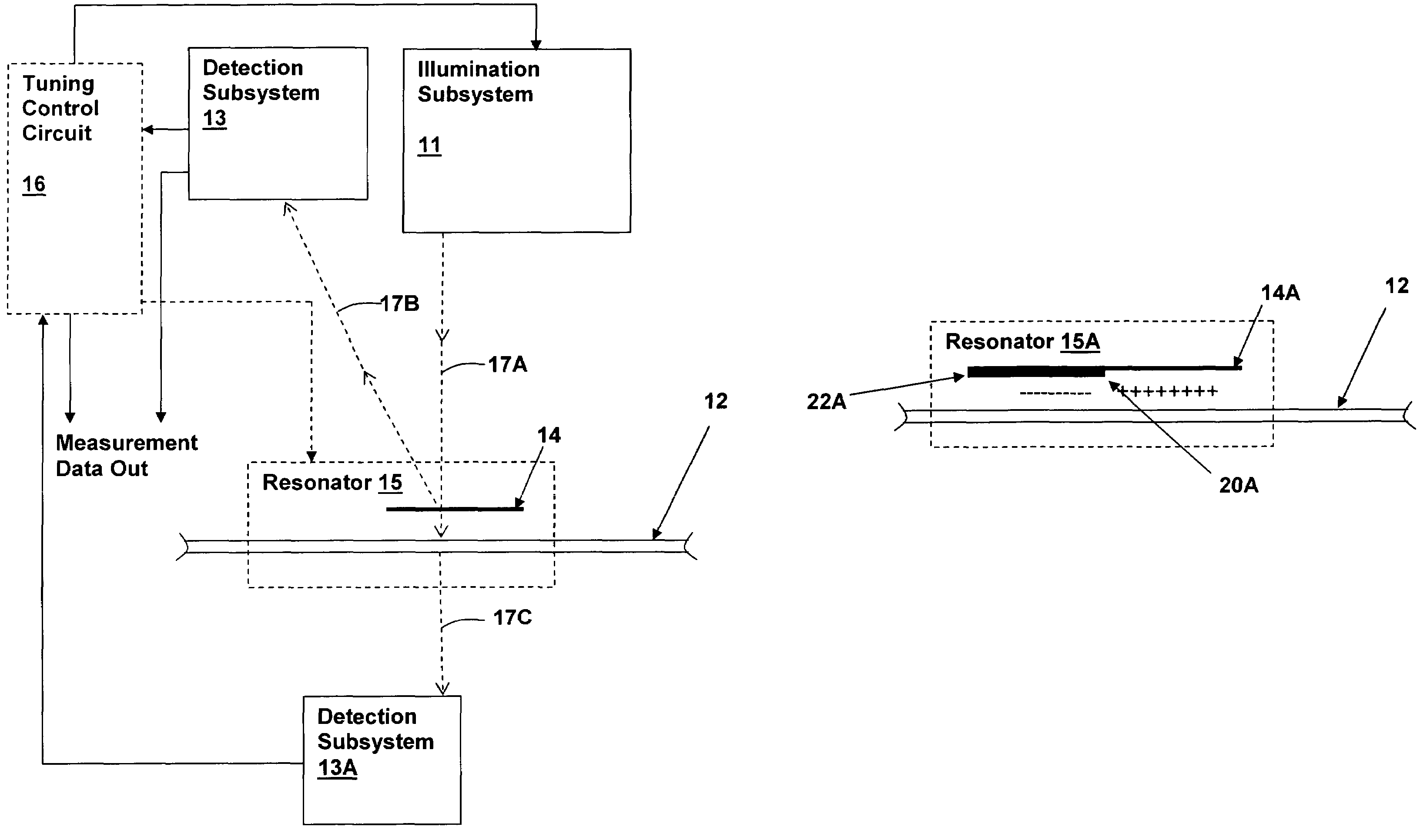
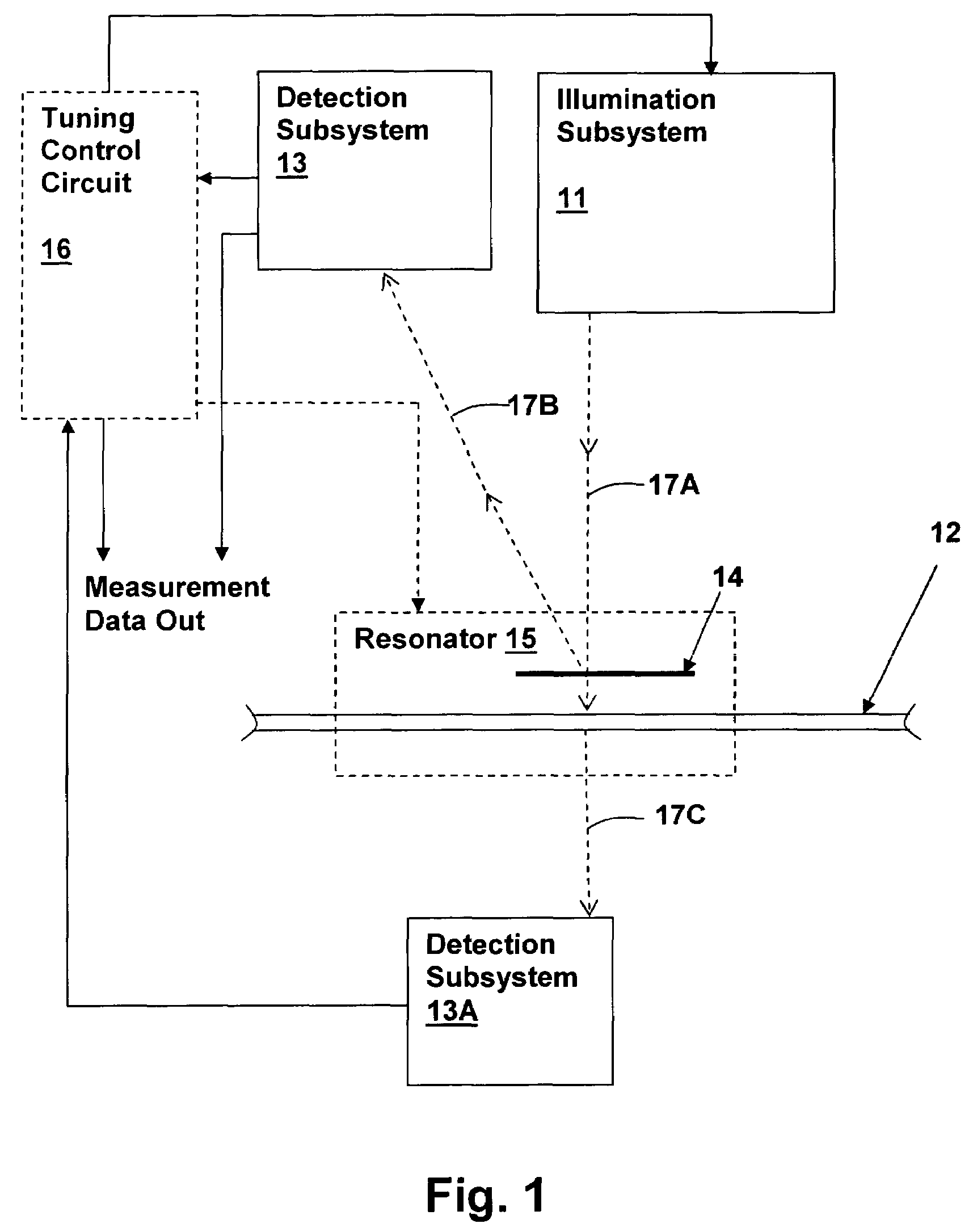
[0021]The above-incorporated Patent and Patent Applications disclose a variety of optical systems and features of optical systems using a Fabry-Perot resonator to improve the resolution of the optical systems. The Fabry-Perot provides improved performance by reducing the spot size of illumination within a resonator that includes the surface of interest within the resonator. By various tuning mechanisms, the Fabry-Perot resonator is tuned to particular operating points to achieve either a narrowed illumination beam, increased resonator sensitivity and / or enhanced selectivity within the measurement.

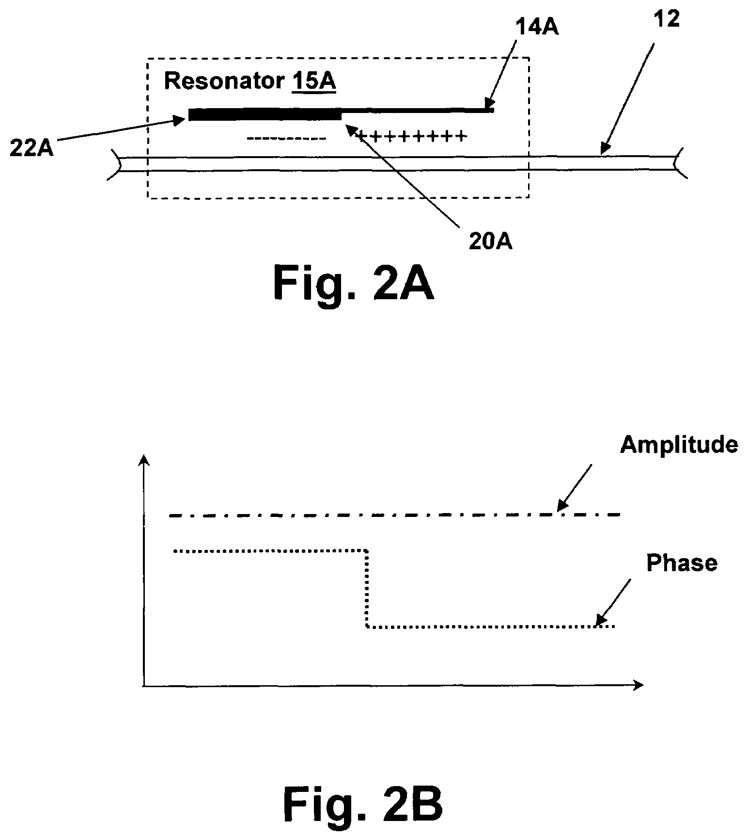
[0022]The present invention concerns an improvement to the above-mentioned Fabry-Perot-enhanced optical systems. A non-uniform illumination phase profile is introduced by modifying at least one surface of the resonator. The non-uniform phase profile further narrows the illumination within the resonator, further enhancing the resolution and other performance characteristics of the optical sy...


PUM

PropertyMeasurementUnit
phase discontinuityaaaaaaaaaa
phase profileaaaaaaaaaa
refractive indexaaaaaaaaaa

Abstract

A method and system for optical measurement via a resonator having a non-uniform phase profile provides a mechanism for measuring and/or detecting sub-micron surface features with increased resolution. A second surface forming part of a resonator is illuminated through a first partially reflective surface that has a non-uniform phase profile that transitions from negative to positive phase with respect to a resonance phase value of the resonator. As a result, a reduced spot size is produced at the second surface, which enhances the resolution of a measurement and/or detection of surface features on the second surface. Additionally, if a discontinuity is provided in the non-uniform phase profile, interaction of the discontinuity with surface features of the second surface will provide enhanced resolution of the surface features. The resolution of the system is improved over the resolution that can be attained using a Fabry-Perot resonator.

Description

CROSS-REFERENCE TO RELATED APPLICATIONS[0001]This application is a Continuation-in-part of U.S. patent application Ser. No. 10 / 403,238, now U.S. Pat. No. 6,778,307, entitled “METHOD AND SYSTEM FOR PERFORMING SWEPT-WAVELENGTH MEASUREMENTS WITHIN AN OPTICAL SYSTEM”, filed on Mar. 28, 2003, which is a Continuation-in-part of U.S. patent application Ser. No. 09 / 789,913, now U.S. Pat. No. 6,522,471 filed Feb. 21, 2001, from which it claims benefit of priority under 35 U.S.C. § 120. The specifications of the above-referenced patent applications are incorporated herein by reference. A parent application of above-incorporated Patent Application entitled “OPTICAL MEASUREMENT AND INSPECTION METHOD AND APPARATUS HAVING ENHANCED OPTICAL PATH DIFFERENCE DETECTION” issued as U.S. Pat. No. 6,653,649 and is incorporated herein by reference. The present application is also related to U.S. patent application Ser. No. 10 / 644,243 entitled “METHOD AND APPARATUS INCLUDING IN-RESONATOR IMAGING LENS FOR IM...

Claims


Application Information

Patent Timeline
Patent Type & Authority Patents(United States)
IPC IPC(8): G01B9/02G01J3/433G01N21/39G02B26/00
CPCG01J3/4338G02B26/001G01N21/39
Inventor BRUNFELD, ANDREICLARK, BRYAN
Owner XYRATEX CORP
Why Eureka
Try Eureka