Lighting device with virtual light source

Active Publication Date: 2017-07-27
SIGNIFY HOLDING B V
View PDF5 Cites 3 Cited by
  • Summary
  • Abstract
  • Description
  • Claims
  • Application Information

AI Technical Summary

Benefits of technology

The patent text talks about the problems with current lighting devices being complicated and expensive to make. The technical effect of the patent is to create a lighting device that is easier and cheaper to produce.

Problems solved by technology

A drawback with such a lighting device is that the optical cover (or envelope) comprising the optical feature for refracting light may be complicated and expensive to manufacture.

Method used


Image

  • Lighting device with virtual light source
  • Lighting device with virtual light source
  • Lighting device with virtual light source

Examples


Embodiment Construction

[0040]The present aspect will now be described more fully hereinafter with reference to the accompanying drawings, in which currently preferred embodiments are shown. This invention may, however, be embodied in many different forms and should not be construed as limited to the embodiments set forth herein; rather, these embodiments are provided for thoroughness and completeness, and fully convey the scope of the present aspect to the skilled person.

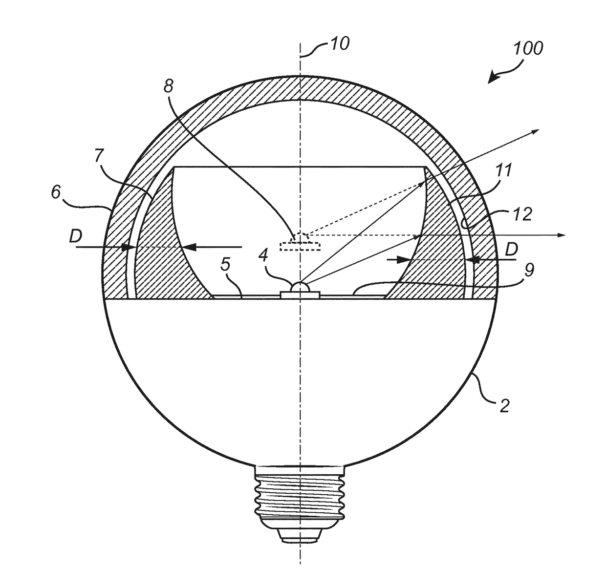
[0041]A lighting device according to an embodiment will be described with reference to FIG. 1. FIG. 1 is a cross-section of a lighting device 100 comprising a base 5, a light source 4 (directly or indirectly) coupled to the base 5 and an envelope (or cover) 6 arranged to cover the light source 4. The envelope 6 may be light transmissive, such as transparent, and may preferably be (directly or indirectly) coupled to the base 5. The envelope 6 may e.g. be shaped as a dome (or bulb). The base 5 and the envelope 6 may together enclose the lig...


PUM


Abstract

A lighting device (1) is provided comprising a base (5), at least one light source (4) arranged at the base, at least one light transmissive optical element (7), and a light transmissive envelope (6) arranged to cover the at least one light source and the at least one optical element. At least a portion of the at least one optical element has a thickness (D) increasing in direction towards the base such that the at least one optical element refracts light emitted by the at least one light source for creating at least one virtual light source (8) spaced from the base. The present aspect is advantageous in that each one of the envelope and the optical element may be manufactured separately, e.g. by standard injection molding technique.

Description

FIELD OF THE INVENTION[0001]The present invention generally relates to the field of lighting devices. In particular, the present invention relates to lighting devices able to provide a virtual light source.BACKGROUND OF THE INVENTION[0002]Traditional incandescent lighting devices have a natural omnidirectional light spreading since the upper portion of the filament is spaced from the screw base of the lighting device. Consequently, light is emitted not just forwardly and laterally, but also backwardly. Conventional solid state based lighting devices, such as light emitting diode (LED) based lighting devices, has a more directed light spreading compared to such incandescent lighting devices since the light source (such as the LED) is itself flat and is normally attached to the base of the lighting device for providing sufficient heat dissipation from the light source via the heat sink arranged at the base. Therefore, the light spreading pattern of LEDs is normally of the Lambertian t...

Claims


Application Information

Patent Timeline
IPC IPC(8): G02B17/02F21V5/04F21V5/02F21K9/232
CPCG02B17/026F21K9/232F21V5/043F21V5/02F21V5/04F21V5/00F21V3/02F21V5/045F21K9/69
Inventor VISSENBERG, MICHEL CORNELIS JOSEPHUS MARIEANSEMS, JOHANNES PETRUS MARIA
Owner SIGNIFY HOLDING B V
Why Eureka
Try Eureka