Device for assembling and adjusting a balance spring

a technology of a balance spring and a terminal coil, which is applied in the direction of instruments, frequency stabilisation mechanisms, frequency setting mechanisms, etc., can solve the problems of extremely fragile and delicate organ structure, very rapid deterioration of chronometric properties, and inability to fully cooperate with the terminal coil of the balance spring. , to achieve the effect of simplifying assembly and adjustmen

Active Publication Date: 2017-07-27
LA MONTRE HERMES
View PDF3 Cites 8 Cited by
  • Summary
  • Abstract
  • Description
  • Claims
  • Application Information

AI Technical Summary

Benefits of technology

[0009]One aim of the invention is to offset the drawbacks of the known devices for assembling and adjusting the balance spring, by proposing such a device maki

Problems solved by technology

One primary drawback of this device comes from the structure of the organs cooperating with the terminal coil of the balance spring.
Indeed, the latter is extremely fragile and delicate, and it its chronometric properties deteriorate very quickly following the mechanical stresses that it may experience.
In the case of this device of the prior art, the mechanical stress that the balance spring may experience, due to its interaction with the striated rotating organ, presents a significant risk of deterioration of its qualities.
In particular, the rotating organ must necessarily apply a certain pre

Method used


Image

  • Device for assembling and adjusting a balance spring
  • Device for assembling and adjusting a balance spring
  • Device for assembling and adjusting a balance spring

Examples


Embodiment Construction

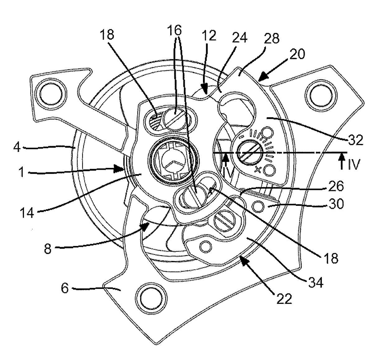
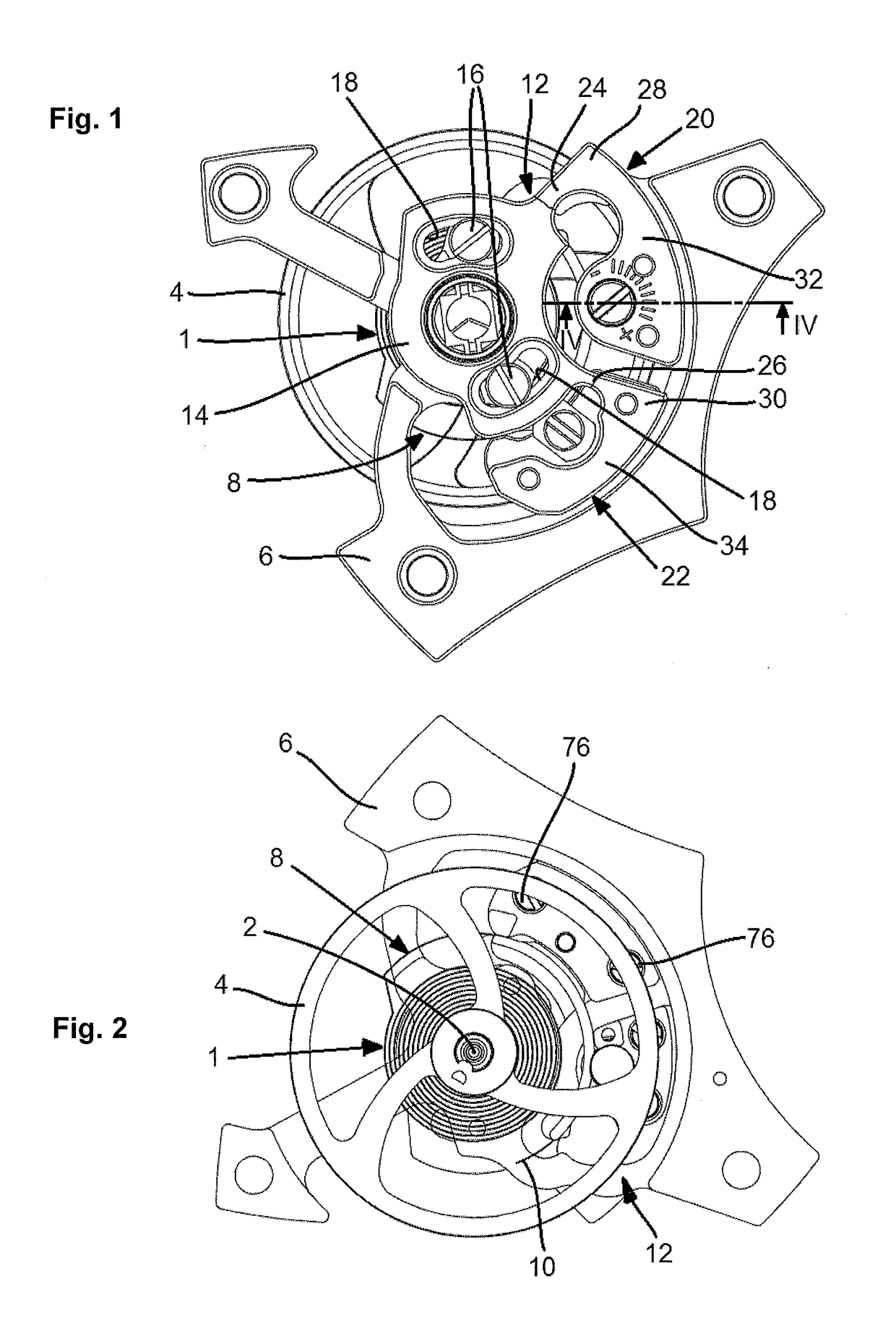
[0029]FIGS. 1 and 2 show general front views of a sprung balance provided with a device for assembling and adjusting the balance spring according to one preferred embodiment of the invention, along first and second respective sides. Typically, the view of FIG. 1 corresponds to a clockwork movement face that would be directly accessible, for example its bar side, while the view of FIG. 2 would be a view of the sprung balance on the plate side.

[0030]Conventionally, a balance spring 1 is fastened to a balance-staff 2 of a balance 4 by its inner end (not shown). The balance-staff 2 has one end mounted pivoting in a balance-cock 6, conventionally.

[0031]The balance spring 1 has a terminal coil 8 leading to its outer end 10.

[0032]The terminal coil 8 cooperates with a device 12 for assembling and adjusting the balance spring.

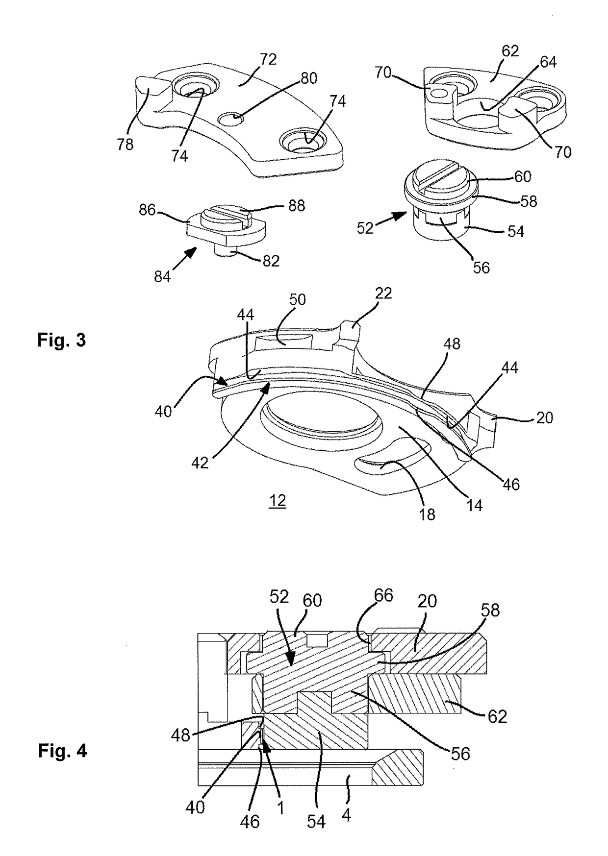
[0033]The device 12 includes a base 14 mounted on the balance-cock 6 with an adjustable angular orientation. To that end, here, as a non-limiting illustration, we have ...


PUM


Abstract

A device for assembling and adjusting a balance spring, comprising a base joined to a balance bridge with an adjustable angular orientation, and comprising a bearing surface and a bearing plate adjacent to the bearing surface, both defining a service position of the end turn of the balance spring. A first arm extends from the base and bears a locking member for the end turn, said locking member being designed to keep the terminal coil in abutment against the bearing surface. The device comprises a second arm that extends from the base and bears a shoe that is able to be arranged at a predefined distance from the bearing surface so as to cooperate with the end turn. A movable control member is able to act on the second arm in order to deform it elastically and move the shoe with respect to the base in order to free the end turn.

Description

CROSS REFERENCE TO RELATED APPLICATIONS[0001]This application is a §371 national stage entry of International Application No. PCT / EP2015 / 067742, filed Jul. 31, 2015, which claims priority to European Patent Application No. 14179606.0 filed Aug. 1, 2014, the entire content of which is incorporated herein by reference.TECHNICAL FIELD[0002]The present invention relates to a device for assembling and adjusting a balance spring intended to cooperate with a terminal coil of a balance spring whereof the inner end may be secured to a balance-staff of a balance, the latter being pivoted in a balance-cock.[0003]More specifically, the invention relates to such a device including[0004]a base, intended to be assembled to the balance-cock with an adjustable angular orientation, and comprising a substantially cylindrical support surface, with a radius substantially equal to the radius of the terminal coil, and a support sole adjacent to the support surface, the support surface and the support sole...

Claims


Application Information

Patent Timeline
IPC IPC(8): G04B17/32
CPCG04B17/325G04B18/06
Inventor WIEDERRECHT, JEAN MARC
Owner LA MONTRE HERMES
Why Eureka
Try Eureka