
Method for planning and executing real time automated decision support in oil and gas wells

a technology for oil and gas wells and decision support, applied in the direction of borehole/well accessories, program control, survey, etc., can solve the problems of large human error, large downtime, and high cost of drilling and well operations in wells for the oil and gas industry, and achieve the effect of removing or reducing the downtime resulting from human errors

Pending Publication Date: 2017-07-27
EXEBENUS AS
View PDF16 Cites 2 Cited by
  • Summary
  • Abstract
  • Description
  • Claims
  • Application Information

AI Technical Summary

Benefits of technology

The present invention proposes a new method for automatically generating, sharing, and relating to data from a process site, such as a well. This method eliminates the error-prone manual processes currently used for generating well procedures and reduces the need for human validation and quality assurance, resulting in improved efficiency and reduced downtime due to human errors.

Problems solved by technology

Drilling and well operations in wells for the oil and gas industry involves complex and expensive operations.
Despite all efforts, due to the complexity of the operations, a percentage of the operations fail, and are classified as “downtime”.
Such downtime costs, each of the major oil companies, large sums (typically greater than a billion USD) each year.
Root-cause analyses also show that a large portion of the downtime is caused due to human errors, typically a result of poor planning, erroneous use of equipment, incorrect situational awareness or other similar factors.
The current process, thus involves three main manual operations, all with a relatively large error margin and potential for undesired consequences; first, the manual process of preparing a procedure by the well object owner, second, the manual process of preparing a well procedure by the well owner, and third, the human interpretation of the well procedure by the specialists at the well site.

Method used


Image

  • Method for planning and executing real time automated decision support in oil and gas wells
  • Method for planning and executing real time automated decision support in oil and gas wells
  • Method for planning and executing real time automated decision support in oil and gas wells

Examples


Embodiment Construction

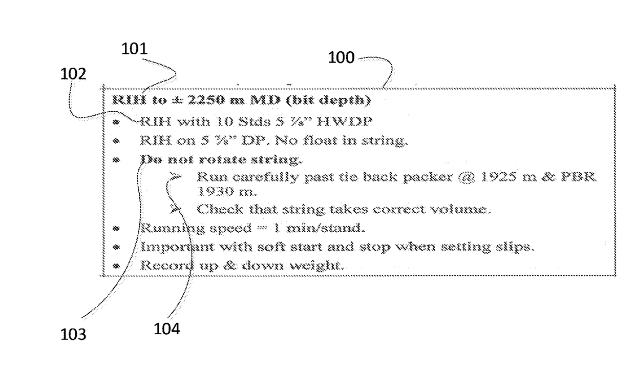
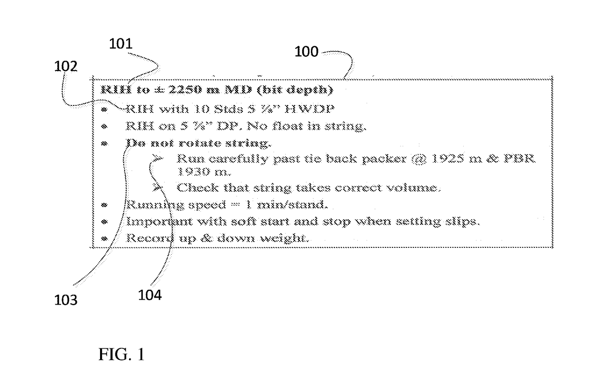
[0029]FIG. 1 show an excerpt from a well procedure 100 as commonly used in the oil and gas industry which may be considered a typical example for a well procedure. The well procedures provide written instructions to the professionals in charge of the operation. The well procedure shows the planned activities in a sequence of order. The specific well procedure 100 as shown in FIG. 1 has grouped the written instructions under a heading 101. The heading 101 belong in the category “main function” as used in the described method, in this case RIH (run in hole), and written instruction corresponds to the term “function”. In this case, for example, instruction 102 belongs in the category of functions in the present invention, whereas instructions 103 and 104 belong in the category “function control” in the proposed method. The instruction 102, “RIH with 10 Stds 5⅞″ HWDP”, describes what to do, i.e., run 10 lengths of HWDP (Heavy Weight Drill Pipe) into the well, whereas “Do not rotate stri...


PUM


Abstract

Method for controlling the state of an operation in a hydrocarbon exploration and recovery environment, including creating at least one function model, said function model including at least one function, executing at least one function within said function model, defining a plurality of function controls, a pre-determined combination of given function controls within said plurality of function controls defining a signature event, an occurrence of said signature event being indicative of a specific state of said operation, and monitoring the occurrence of said signature event during execution of a certain function included in said at least one function model.

Description

BACKGROUND OF THE INVENTION[0001]The present invention generally relates to the operation of pipes, tubulars and tools in oil and gas wells.[0002]Drilling and well operations in wells for the oil and gas industry involves complex and expensive operations. A large manpower is typically used to manage and controls these operations. Despite all efforts, due to the complexity of the operations, a percentage of the operations fail, and are classified as “downtime”. Such downtime costs, each of the major oil companies, large sums (typically greater than a billion USD) each year. Research and operational benchmarking show that automated decision support and automated operations provide a consistently higher quality performance than can be achieved by manual operations. Root-cause analyses also show that a large portion of the downtime is caused due to human errors, typically a result of poor planning, erroneous use of equipment, incorrect situational awareness or other similar factors. In ...

Claims


Application Information

Patent Timeline
Patent Type & Authority Applications(United States)
IPC IPC(8): G05B19/4155E21B44/02
CPCG05B19/4155G05B2219/45129E21B44/02E21B44/00G05B17/02E21B47/00
Inventor REVHEIM, OLAV
Owner EXEBENUS AS
Learn More