Train derailer placement warning device

a technology for warning devices and trains, applied in railway signalling, signalling indicators on vehicles, transportation and packaging, etc., can solve problems such as accidents, improvements that fall short of providing assurance of an active warning whenever a derailer is thrown off, and sections of tracks may simply be shut down

Active Publication Date: 2017-08-03
GREEN TIMBER ENERGY
View PDF5 Cites 5 Cited by
  • Summary
  • Abstract
  • Description
  • Claims
  • Application Information

AI Technical Summary

Problems solved by technology

In addition, sections of track may simply be shut down due to condition or other factors.
Unfortunately, this type of warning relies upon workers to properly place the flags or blinking lights and to properly remove or deactivate the derailer when the flags and blue lights have been removed.
This is not always the case, and accidental derailings have occurred due to work crews forgetting to remove or deactivate a derailer after removing the flags and blue lights.
While some derailers have been designed to incorporate devices that automatically elevate a blue flag upon activation on a section of tracks, and other derailer systems have been devised to allow for remote activation of warning blue lights for the derailers, these improvements still fall short of providing assurance of an active warning whenever a derailer is placed and active on a set of tracks.

Method used


Image

  • Train derailer placement warning device
  • Train derailer placement warning device
  • Train derailer placement warning device

Examples


second embodiment

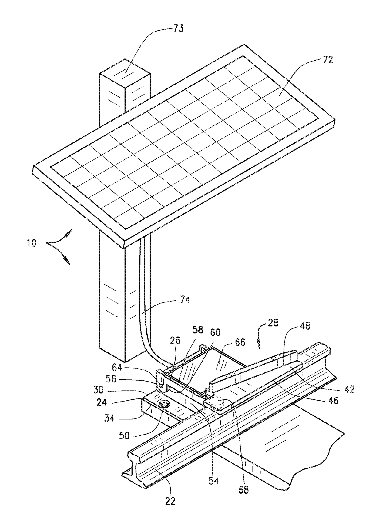
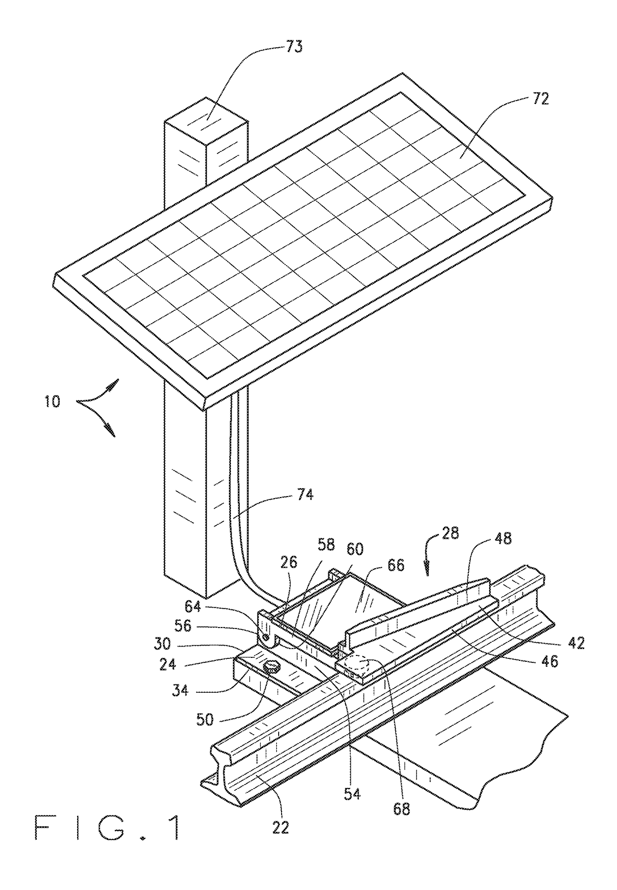
[0032]Referring now to FIG. 5, the present invention is shown also incorporated into a portable derailer at 100. Here, the portable derailer 100 includes a flat, rectangular heavy-gage steel upper plate 122, a heavy-gage steel derail component or wedge 124 that rises vertically from the top of the upper plate 122, and two parallel, perpendicular heavy-gage steel mounting plates 126 and 127 that extend perpendicularly downward from opposite sides of the upper plate 122. The upper plate 122 has a first short edge 128 and a second short edge 130 that is parallel to the first short edge 128. The upper plate 122 also has a first long edge 132 and a second long edge 134 that is parallel to the first long edge 132.

[0033]The mounting plate 126 is welded along its upper edge at a perpendicular angle to the first long edge 132 of the upper plate 122. Similarly, the mounting plate 127 is welded along its upper edge at a perpendicular angle to the second long edge 134 of the upper plate 122. Th...

third embodiment

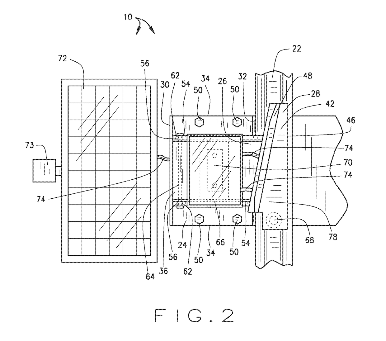
[0040]Referring now to FIG. 6, the present invention is shown also incorporated into a permanent derailer at 200. Here, as can be seen by comparing FIG. 5 to FIG. 1, the derailer 200 incorporates most of the same components as the derailer 10. However, for the derailer 200, the LED panel 66 is fixedly attached to the side of the stake 73 instead of being fixedly attached to the upper surface of the neck plate 26. Also, the derailer 200 has a battery 202 positioned within a housing 204 that is also fixedly attached to the side of the stake 73. Electric cables (shown in part at 74) interconnect the battery 202 a wireless receiver 206 also positioned within the housing 204, the solar charger 72, and the LED panel 66, such that the solar charger 72 maintains an electric charge in the battery 202 and the solar charger 72 and the battery 202 can independently or collectively power the wireless receiver 206 and the LED panel 66. While one of ordinary skill in the art will recognize that th...

fourth embodiment

[0042]Referring now to FIG. 7, the present invention is shown also incorporated into a permanent derailer at 300. Here, as can be seen by comparing FIG. 5 to FIG. 1, the derailer 300 incorporates most of the same components as the derailer 10. However, for the derailer 300, the solar charger 72 is fixedly attached in an upward facing manner by a pair of arms 302 to the proximal end 30 of the base plate 24.

[0043]While I have described in the detailed description several configurations that may be encompassed within the disclosed embodiments of this invention, numerous other alternative configurations, that would now be apparent to one of ordinary skill in the art, may be designed and constructed within the bounds of my invention as set forth in the claims. Moreover, the above-described novel derailer placement warning device of the present invention can be arranged in a number of other and related varieties of configurations without departing from or expanding beyond the scope of my ...


PUM


Abstract

A derail placement warning system for a railway derailer that automatically generates an alert to inform railway personnel (or others) of the placement of the derailer on a rail of the railway such that the derailer will derail rail traffic over the derailer. The warning system has an electronic circuit with an electric power source, an electronic switch and an electronic alert, and is configured for the switch to automatically activate and turn ON the alert when the derailing component of the derailer is positioned atop a railway rail. The alert comprises one or more of an audible component, a tactile sensation, an olfactory component, a visible light emission, and an electronic transmission.

Description

CROSS REFERENCE TO RELATED APPLICATIONS[0001]This application claims the benefit of U.S. Provisional Application No. 62 / 288,879, entitled TRAIN DERAILER PLACEMENT WARNING DEVICE, filed on Jan. 29, 2016. The disclosure of the above application is incorporated herein by reference.STATEMENT REGARDING FEDERALLY SPONSORED RESEARCH OR DEVELOPMENT[0002]Not applicable.BACKGROUND OF THE INVENTION[0003]This invention relates generally to a device or system for alerting a train or other movable rail equipment in motion on a set of tracks when said train or rail equipment is in proximity to a derailer positioned on the tracks, and more particularly to a device or system that actively produces a signal to the train or rail equipment passing near the device warning of the proximity of the derailer on the tracks.[0004]In the railroad industry it is often necessary to conduct maintenance or repairs of various sections of rail or tracks. This is particularly relevant in high rail traffic locations, ...

Claims


Application Information

Patent Timeline
Patent Type & Authority Applications(United States)
IPC IPC(8): B61L15/00B61L23/04B61K5/06
CPCB61L15/0018B61K5/06B61L2205/00B61L23/042B61L15/009B61L5/1809B61L5/189B61L23/00B61L2207/02
Inventor MCCARTHY, JOHN
Owner GREEN TIMBER ENERGY
Why Eureka
Try Eureka