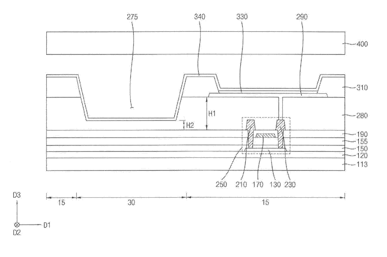
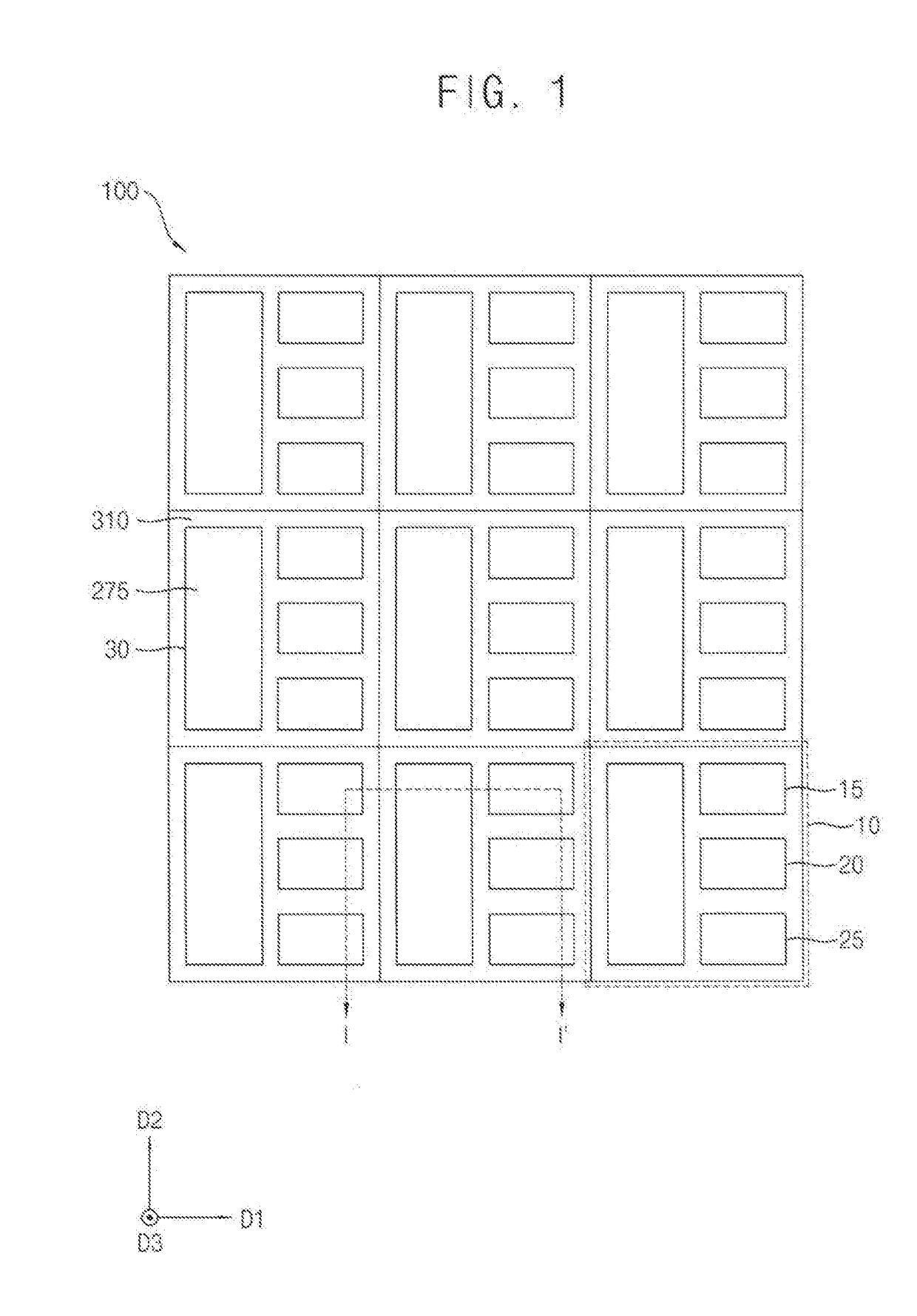
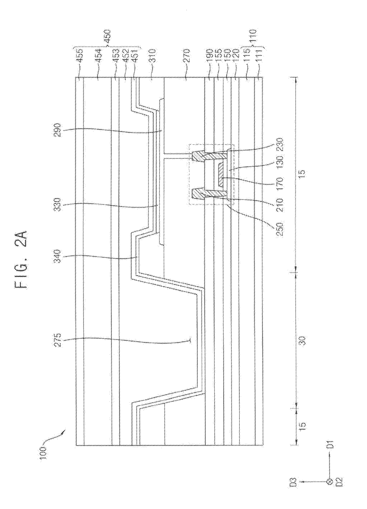
Display device

a display device and transparent region technology, applied in the field of display devices, can solve the problems of undesirable change of color characteristics of light transmitted through the transparent region, negative influence of electron mobility of the active layer, and unsatisfactory transmissivity of the transparent region, etc., to achieve satisfactory transmittance of the transparent region of the display device, satisfactory electron mobility in the switching element, and satisfactory performance of the display device

Active Publication Date: 2017-08-03
SAMSUNG DISPLAY CO LTD
View PDF2 Cites 26 Cited by
  • Summary
  • Abstract
  • Description
  • Claims
  • Application Information

AI Technical Summary

Benefits of technology

[0078]In a display device (e.g., an OLED device) according to embodiments, refractive indexes of immediately neighboring insulation layers may be substantially equal. Advantageously, the transmittance of a transparent region of the display device may be satisfactory. In embodiments, a display device (e.g., an OLED device) includes one or more insulation layers that enable desirable interface characteristics of an active layer in a switching element of the display device. Advantageously, electron mobility in the switching element may be satisfactory, such that performance of the display device may be satisfactory.

Problems solved by technology

Therefore, transmissivity of the transparent region may be unsatisfactory.
In addition, color characteristics associated with a light transmitted via the transparent region may be undesirably changed.
One or more of the insulation layers may be based on nitride, may directly contact an active layer of the display device, and may negatively affect electron mobility of the active layer, such that performance of the display device may be unsatisfactory.

Method used


Image

  • Display device
  • Display device
  • Display device

Examples


experimental example

ittances Varying Insulation Layer Structures

[0191]A barrier layer, a buffer layer, a first gate insulation layer, a second gate insulation layer, a first insulating interlayer, and a second insulating interlayer, each of which included stacked silicon oxide layer and silicon oxynitride layer were sequentially formed on a polyimide substrate having a thickness of 10 micrometers to obtain stacked structures of Comparative Example (refer to FIG. 15).

[0192]A barrier layer having a single composition of silicon oxynitride, a buffer layer having a single composition of silicon oxide, a first gate insulation layer having a single composition of silicon oxide, a second gate insulation layer having a single composition of silicon oxynitride, a first insulating interlayer having a single composition of silicon oxynitride, and a second insulating interlayer having a single composition of silicon oxynitride were sequentially formed on the polyimide substrate to obtain a stacked structure of Exa...


PUM


Abstract

A display device may include a light emitting element, a buffer layer, a gate insulation layer, and a switching element. A refractive index of the gate insulation layer may be equal to a refractive index of the buffer layer. The switching element may be electrically connected to the light emitting element and may include an active layer and a gate electrode. The active layer may be positioned between the buffer layer and the gate insulation layer and may directly contact at least one of the buffer layer and the gate insulation layer. The gate insulation layer may be positioned between the active layer and the gate electrode and may directly contact at least one of the active layer and the gate electrode.

Description

CROSS-REFERENCE TO RELATED APPLICATION(S)[0001]This application claims priority under 35 USC §119 to Korean Patent Application No. 10-2016-0011355, filed on Jan. 29, 2016 in the Korean Intellectual Property Office (KIPO); the contents of the Korean Patent Application are incorporated herein in by reference.BACKGROUND[0002]1. Field[0003]The technical field is related to a display device, e.g., an organic light emitting display device.[0004]2. Description of the Related Art[0005]Various display devices have been widely used in electronic devices. Display devices may include liquid crystal display (LCD) devices and organic light emitting display (OLED) devices.[0006]A display device, such as an OLED device, may include a substantially transparent region for showing an object (or a target) that is located in the rear (e.g., the back) of the display device. The display device may also include a pixel region that can emit light for displaying an image. Multiple insulation layers may be di...

Claims


Application Information

Patent Timeline
Patent Type & Authority Applications(United States)
IPC IPC(8): H01L27/32H01L51/52H01L51/00
CPCH01L27/3262H01L29/78645H01L27/3258H01L27/3248H01L51/0096H01L51/5275H01L51/5256H01L27/3246H01L29/78666H01L29/78675H01L27/1222H01L27/1248H01L2251/301H01L29/513H01L27/3211H10K59/88H10K59/12H10K59/10Y02E10/549Y02P70/50H10K59/121H10K59/1213H10K77/111H10K50/858H10K50/844H10K59/1201H10K50/8445H10K59/35H10K59/122H10K59/123H10K59/124H10K77/10H10K2102/00
Inventor PARK, HYE-HYANGJEON, JOO-HEEJUNG, SEUNG-HOCHOI, CHAUN-GIKIM, HYEON-SIKYANG, HUI-WONLEE, EUN-YOUNG
Owner SAMSUNG DISPLAY CO LTD
Why Eureka
Try Eureka