Massive-mimo antenna measurement device and method of measuring directivity thereof

a technology of mass-mimo antenna and measurement device, which is applied in the direction of transmitter monitoring, instruments, transmission monitoring, etc., can solve the problems of further increase in attenuation and drastically shorten the time spent in constructing a measurement system, and achieve the effect of high degree of accuracy

Active Publication Date: 2017-08-03
ANRITSU CORP
View PDF3 Cites 18 Cited by
  • Summary
  • Abstract
  • Description
  • Claims
  • Application Information

AI Technical Summary

Benefits of technology

The present invention provides a method for accurately measuring the direction of a beam of a test antenna. This is achieved by causing the probe antenna to scan the measurement plane and obtain the virtual directivity of the test antenna, which is then corrected by the angle at which the test antenna is directed. This allows for accurate measurement of the beam direction regardless of its direction in relation to the measurement plane. The technical effect of this invention is to provide a reliable and accurate means for measuring the direction of a beam.

Problems solved by technology

The technical problem addressed in this patent text is the need for a method to measure the directivity of an antenna in a way that is accurate and efficient, particularly in the case of a massive-MIMO antenna. The text describes a technique called near field measurement (NFM) that uses a probe antenna to scan the surrounding area and measure the electromagnetic field distribution, which can be used to calculate the far field directivity of the antenna. The NFM has advantages over far field measurement (FFM) in terms of faster measurement and accuracy, but requires a compact device and a small-scale anechoic chamber for its use. The text also describes a measurement device that performs the NFM using a plane NFM and a probe scanning mechanism.

Method used


Image

  • Massive-mimo antenna measurement device and method of measuring directivity thereof
  • Massive-mimo antenna measurement device and method of measuring directivity thereof
  • Massive-mimo antenna measurement device and method of measuring directivity thereof

Examples


Embodiment Construction

[0051]Hereinafter, an embodiment of the present invention will be described with reference to the accompanying drawings.

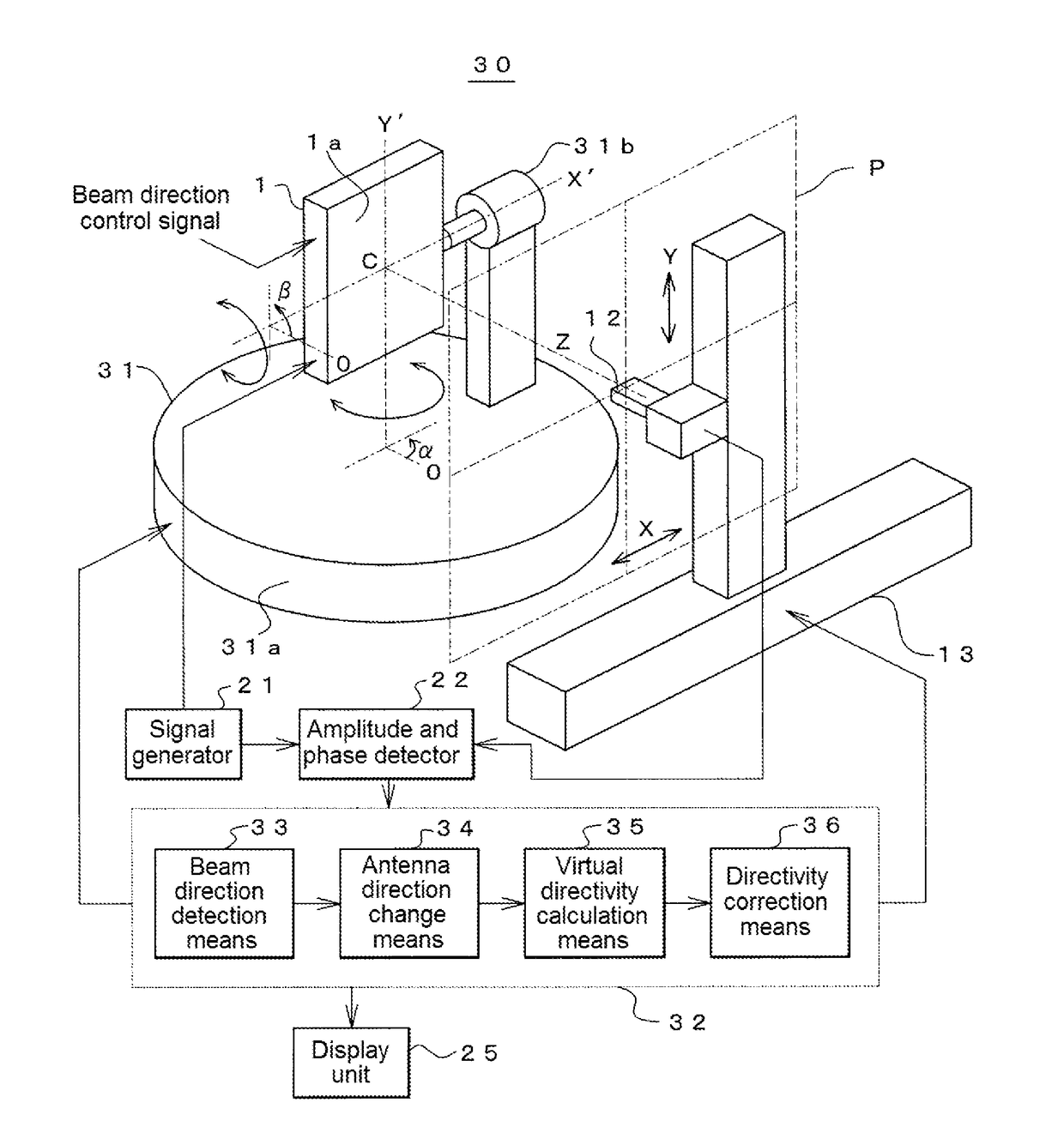
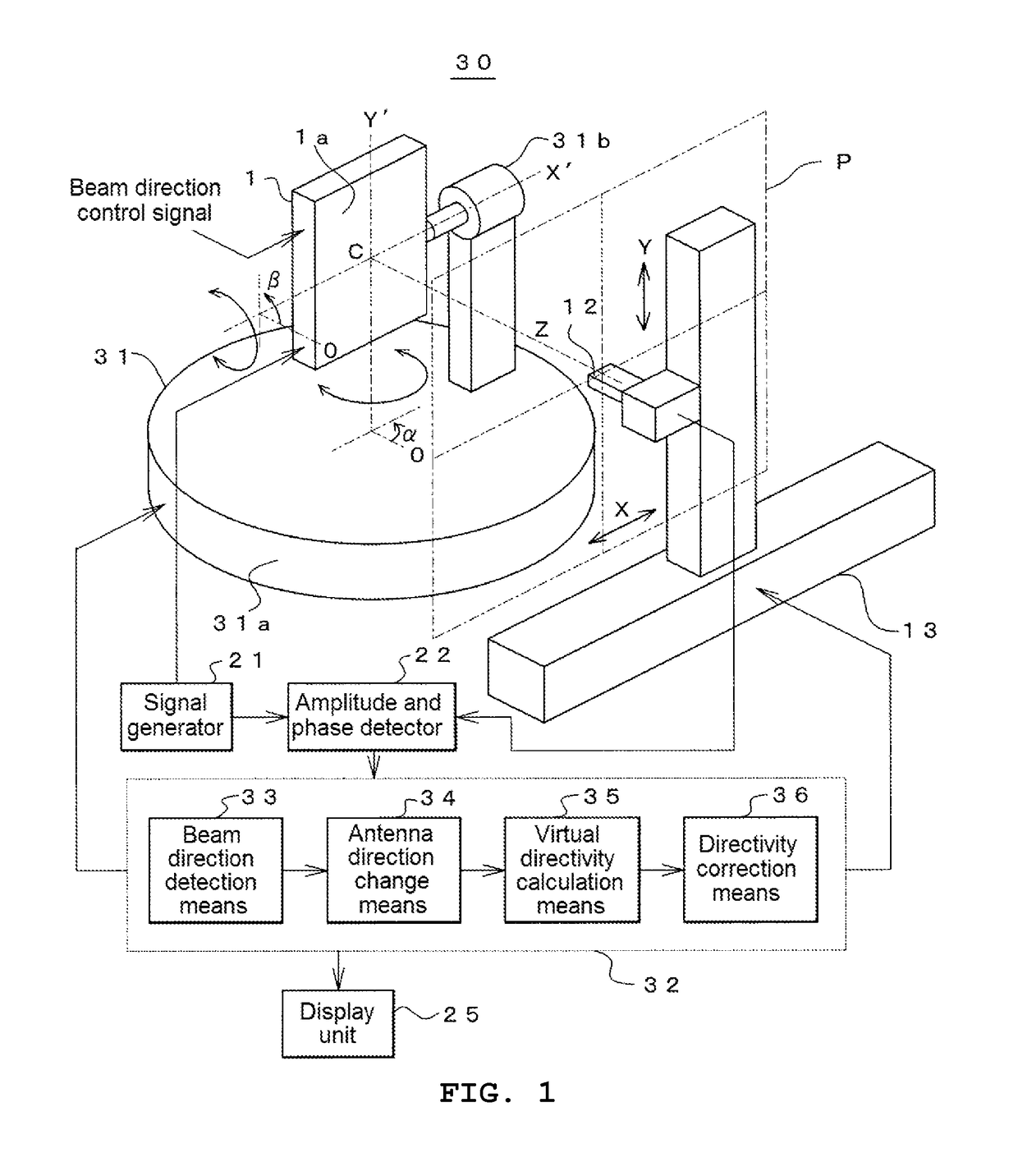
[0052]FIG. 1 shows a configuration of a massive-MIMO antenna measurement device (hereinafter, simply referred to as a measurement device) 30 to which the present invention is applied.

[0053]This measurement device 30 includes a test antenna support portion 31 and a measurement control unit 32, in addition to the probe antenna 12, the probe scanning mechanism 13, the signal generator 21, the amplitude and phase detector 22, and the display unit 25 which are described in the aforementioned device 10 of the related art.

[0054]This measurement device 30 is a device that measures the directivity of the test antenna 1 which is used as a massive-MIMO antenna, and is configured herein such that the test antenna 1 is used as a planar array antenna having a plurality of antenna elements arranged lengthwise and crosswise, a power feeding phase for each antenna element is contro...


PUM


Abstract

To minimize a measurement range when a near field measurement is performed on the directivity of a massive-MIMO antenna, and prevent the accuracy of measurement from deteriorating. Beam direction detection means 33 causes a probe antenna 12 to perform a rough scanning in a state where an electromagnetic wave radiation plane 1a of a test antenna 1 is directed toward a reference direction directly facing a measurement plane P, and detects the direction of a beam radiated by the test antenna 1 on the basis of a received signal thereof. Antenna direction change means 34 changes the direction of the test antenna so that the detected direction of a beam is directed toward the center of the measurement plane P.

Description


Claims


Application Information

Patent Timeline
Owner ANRITSU CORP
Why Eureka
Try Eureka