Network Data Stream Tracer

a network data and tracer technology, applied in the field of data networking, can solve the problems of insufficient internal buffering resources, incorrect programming, and inability to program correctly, and achieve the effect of minimizing the harmful impact of network elements los

Active Publication Date: 2017-08-03
ARISTA NETWORKS
View PDF10 Cites 50 Cited by
  • Summary
  • Abstract
  • Description
  • Claims
  • Application Information

AI Technical Summary

Benefits of technology

[0005]To minimize the harmful impact of lost network elements, embodiments described herein provide for a network element having logic to quickly identify when a network element is misforwarding traffic, allowing corrective action can be taken. In one embodiment a network element includes forwarding logic to forward a unit of network data from an ingress interface to an egress interface and stream tracer logic to cause marking logic to mark selected units of network data for counting via counting logic. The stream tracer logic causes the counting logic to count the marked units of network data at an ingress point and an egress point of a detection region within the forwarding logic, the counting logic to generate an ingress count and an egress count for the detection region, wherein the stream tracer logic is to detect whether units of network data are dropped within the detection region via a count of the marked units of network data.

Problems solved by technology

A network can drop a unit of network data when the network data should have been forwarded for a number of reasons including software bugs, insufficient internal buffering resources, or incorrect programming of switch state due to software or firmware problems.
Additionally incorrect programming can arise due to errors on one or more buses that connect the network element to the controlling software.
Furthermore, spontaneous errors in the state used for forwarding data can occur because of, for example, hardware bugs, corruption on internal buses internal to the forwarding hardware, bit flips on account of cosmic rays in forwarding tables or buffers, failing memories or logic caused by manufacturing defects, age, temperature, or physical stress.
Additionally, improper mechanical connections between line cards and fabric cards can result in bit errors on the internal connections of the network element.

Method used


Image

  • Network Data Stream Tracer
  • Network Data Stream Tracer
  • Network Data Stream Tracer

Examples


Embodiment Construction

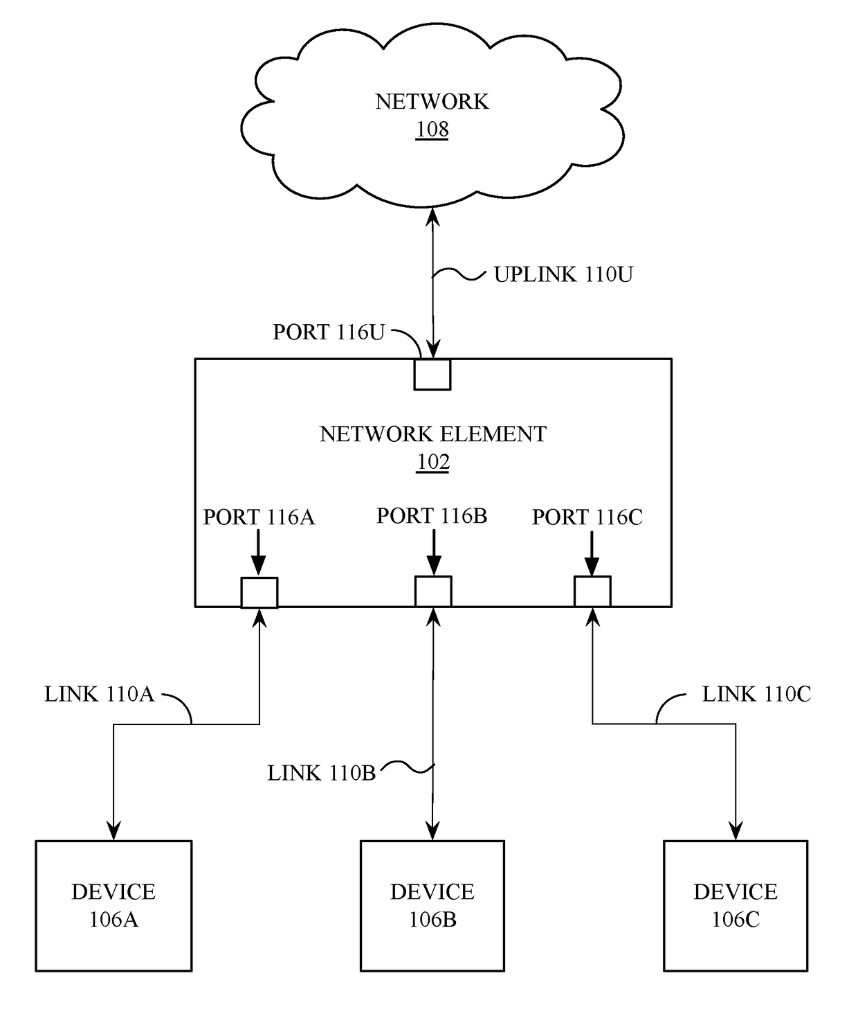
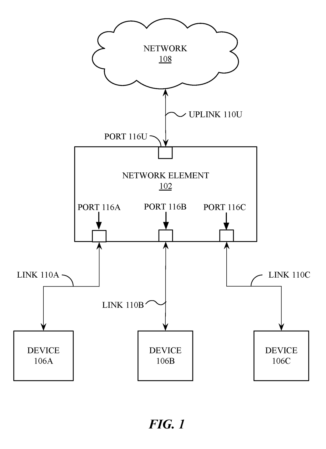
[0026]In one embodiment, a stream tracer identifies “streams” of network data (e.g., packets, frames, datagrams, etc.) within a network element (e.g., switch, router, bridge, gateway, etc.) and counts any drops in the stream. A simplified version of the stream tracer may be configured to perform “boundary accounting,” in which a boundary is defined within a network element and the ingress and egress counters at the boundary are read and compared. The ingress and egress counters can be configured to count all network data interesting and exit the boundary and compare the collective counters.

[0027]However, identifying a boundary where the ingress and egress counters are expected to exactly match and that covers enough of the system to catch a large fraction of errors is significantly challenging for several reasons. The ingress or egress boundary may have multiple ingress or egress points. Computing the total number of boundary crossings involves summing a set of multiple counters on ...


PUM


Abstract

Various embodiments of a network element comprising a control plane including stream tracer logic are described herein. The network element additionally includes a data plane coupled to the control plane, where the data plane includes forwarding logic to forward a unit of network data from an ingress interface to an egress interface. The stream tracer logic can be configured to cause marking logic to mark selected units of network data for to be counted by counting logic and to cause the counting logic to count marked units of network data. The stream tracer logic can determine whether units of network data are dropped within the forwarding logic via comparison of an ingress count of the marked units of network data with an egress count of the marked units of network data.

Description

RELATED APPLICATIONS[0001]Applicant claims the benefit of priority of prior, co-pending provisional application Ser. No. 62 / 288,145, filed Jan. 28, 2016, the entirety of which is hereby incorporated herein by reference.FIELD OF INVENTION[0002]This invention relates generally to data networking and more particularly to the tracing if network data streams within a network element.BACKGROUND OF THE INVENTION[0003]A network element (such as a router or switch) transmits and receives network data using one or more ports of that network element. For each incoming unit of network data (e.g., packet, frame, datagram, etc.), the network element makes a forwarding decision, considering user configuration, the contents of the packet, the state of the switch, including “forwarding tables”, and negotiated protocol information. The forwarding decision indicates whether the unit of network data is to be dropped or forwarded, and if so, to which port (or ports) the unit of network data is to be for...

Claims


Application Information

Patent Timeline
Patent Type & Authority Applications(United States)
IPC IPC(8): H04L12/24H04L12/713H04L12/741H04L45/586H04L45/74
CPCH04L41/12H04L45/586H04L45/745H04L43/0835H04L43/0876
Inventor HOLBROOK, HUGHLABONTE, FRANCOISDUDA, KENNETH
Owner ARISTA NETWORKS
Why Eureka
Try Eureka