Supercharge Your Innovation With Domain-Expert AI Agents!

Processing a disparity of a three dimensional image

a three-dimensional image and disparity processing technology, applied in the field of disparity processing, can solve the problems of increasing data, inability to provide ideal performance, and inability to achieve the effect of reducing disparity artefacts

Active Publication Date: 2017-08-03
KONINKLJIJKE PHILIPS NV
View PDF3 Cites 3 Cited by
  • Summary
  • Abstract
  • Description
  • Claims
  • Application Information

AI Technical Summary

Benefits of technology

The invention provides an improved way to create three-dimensional images that can reduce errors and inaccuracies. This is particularly useful for images that have been generated using stereo images and may include overlay graphics like subtitles or text. The invention can make the image look better and make it easier to see the details.

Problems solved by technology

However, as this may be considered inconvenient to the user, it is in many scenarios preferred to use autostereoscopic displays that use means at the display (such as lenticular lenses, or barriers) to separate views, and to send them in different directions where they individually may reach the user's eyes.
However, a significant problem is that the additional information results in substantially increased amounts of data, which is impractical for the distribution, communication, processing and storage of the video data.
However, although disparity estimation may be useful for determining depth information in many situations, it tends to not provide ideal performance and the generated depth information may be quite noisy and comprise inaccuracies.
However, it also results in new artifacts caused by the filtering operation.
This causes disparity variations over the object, and results in distorted edges in synthesized views.
These distortions are disturbing for a human observer, as our human visual system is particularly sensitive to (distortions in) straight edges.
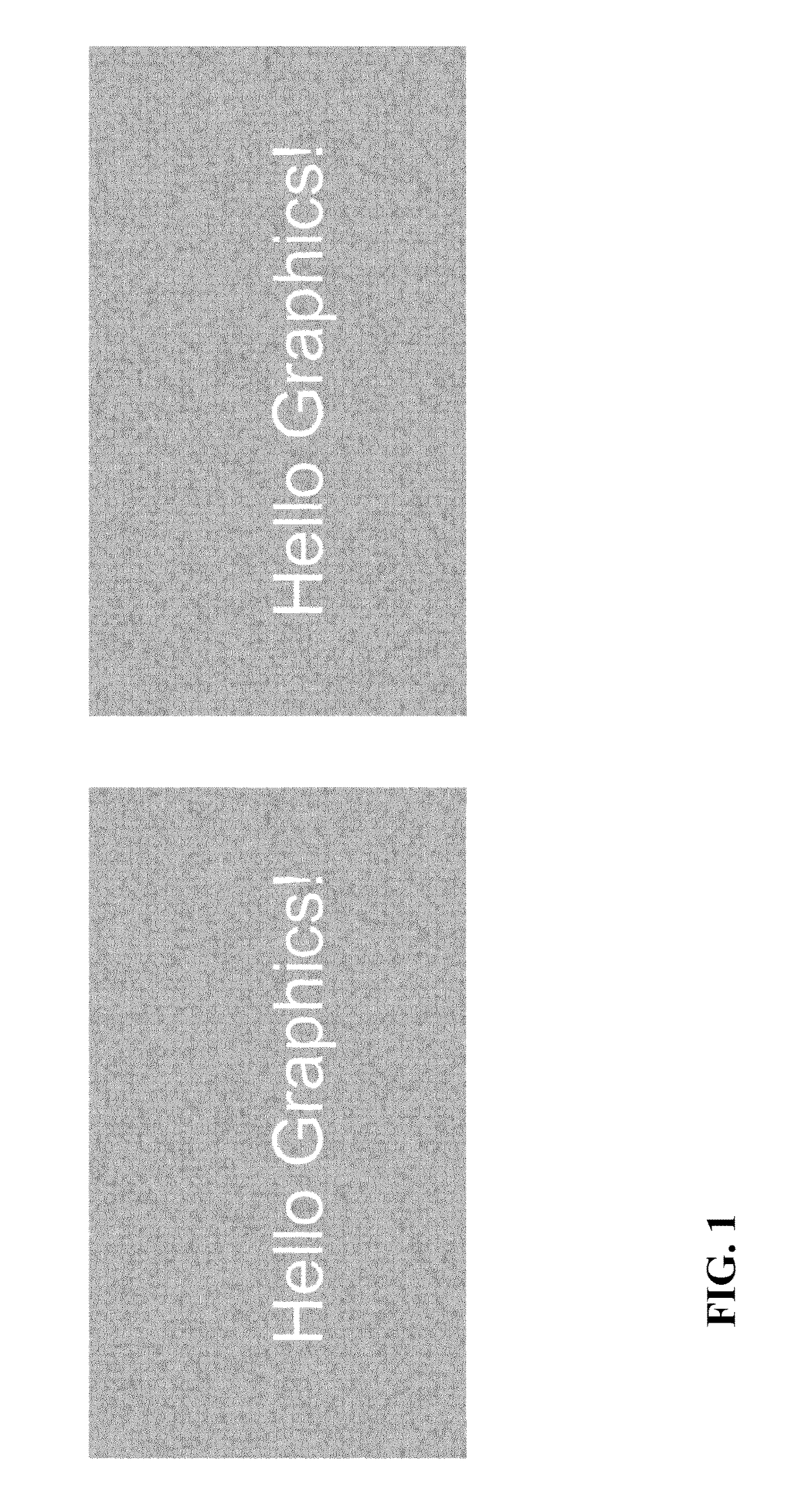
Such distortions may cause a significant perceived quality reduction by a human observer, such as e.g. when graphics overlays are present.
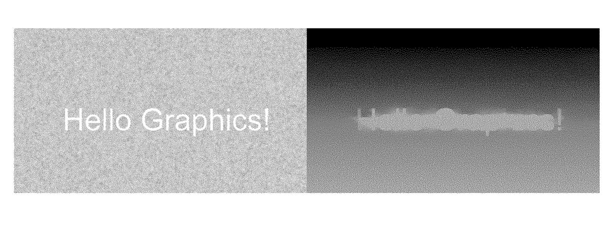
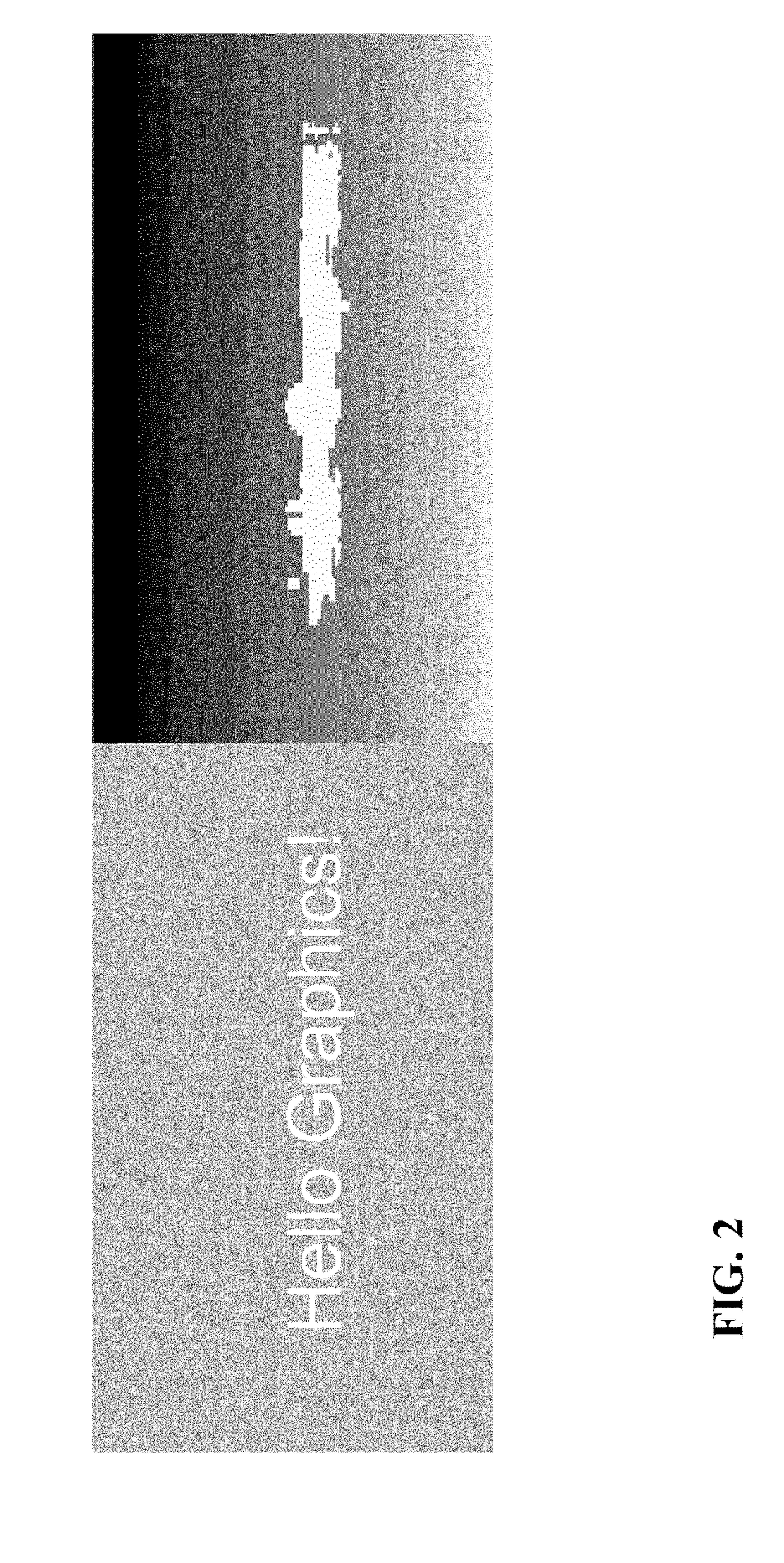
Although the disparity map is less blocky and appears smoother, there are still substantial disparity errors in the area around the text.
Similar depth and disparity artefacts may arise for other approaches of generating depth information for three dimensional images, and may degrade perceived quality of the resulting three dimensional images that are presented to a user.

Method used


Image

  • Processing a disparity of a three dimensional image
  • Processing a disparity of a three dimensional image
  • Processing a disparity of a three dimensional image

Examples


Embodiment Construction

[0067]The following description will focus on embodiments wherein an input three dimensional image is processed based on an estimation of whether the image comprises overlay graphics or not. However, it will be appreciated that the invention is not limited to such an embodiment or application but may be applicable to many different applications and images.

[0068]FIG. 4 illustrates an apparatus for processing a three dimensional (3D) image.

[0069]The apparatus comprises a receiver 401 which is arranged to receive a 3D image. The 3D image is made up of pixels and each of these pixels is associated with an image value indicative of the visual light radiating from the object seen at that position and a disparity value indicative of the depth of the object in the scene.

[0070]The receiver may for example be a network interface, a media reader, an optical disc reader, a television receiver etc. or indeed may be implemented as any suitable hardware capable of receiving image data from a suita...


PUM


Abstract

An apparatus for reducing the visibility of disparity estimation errors at edges, and in particular at overlays. The apparatus comprises a receiver (401) for receiving a three dimensional image represented by at least image values (brightness / contrast values) and a disparity value. A subset selector (403) evaluates an image property criterion for the image value for a group of pixels and determines a subset of pixels of the group of pixels for which the image property criterion is met. The criterion may for example reflect whether the pixel belongs to an image object edge. A distribution evaluator (405) generates a frequency distribution for disparity values of the subset of pixels and an analyzer (407) determines a shape property for the frequency distribution (the presence of a peak). An adaptor (409) determining a disparity remapping in response to the shape property and a remapper (411) modifies disparity values of the three dimensional image by applying the disparity remapping. The approach may e.g. reduce image depth when overlay graphics is likely to be present.

Description

FIELD OF THE INVENTION[0001]The invention relates to processing of a three dimensional image, and specifically, but not exclusively, to disparity processing for three dimensional images comprising graphic overlays.BACKGROUND OF THE INVENTION[0002]Three dimensional (3D) displays add a third dimension to the viewing experience by providing a viewer's two eyes with different views of the scene being watched. This can be achieved by having the user wear glasses to separate two views that are displayed. However, as this may be considered inconvenient to the user, it is in many scenarios preferred to use autostereoscopic displays that use means at the display (such as lenticular lenses, or barriers) to separate views, and to send them in different directions where they individually may reach the user's eyes. For stereo displays, two views are required whereas autostereoscopic displays typically require more views (such as e.g. nine views).[0003]In order to fulfill the desire for 3D image ...

Claims


Application Information

Patent Timeline
Patent Type & Authority Applications(United States)
IPC IPC(8): H04N13/00H04N13/122
CPCH04N13/0018H04N13/0022H04N2213/003H04N2013/0092H04N2013/0081H04N13/128H04N13/122
Inventor VAREKAMP, CHRISTIAANVANDEWALLE, PATRICK LUC ELS
Owner KONINKLJIJKE PHILIPS NV
Features
  • R&D
  • Intellectual Property
  • Life Sciences
  • Materials
  • Tech Scout
  • Unparalleled Data Quality
  • Higher Quality Content
  • 60% Fewer Hallucinations
Learn More