
Method of making a dental prosthesis

a dental prosthesis and dental technology, applied in dental prosthesis, dentistry, medical science, etc., can solve the problems of time-consuming and costly, falling out of consideration for individual patients, etc., and achieve the effect of reducing the time expenditure of patients

Inactive Publication Date: 2017-08-10
BREDENT
View PDF1 Cites 0 Cited by
  • Summary
  • Abstract
  • Description
  • Claims
  • Application Information

AI Technical Summary

Benefits of technology

The invention provides a method for making dental prostheses or adapting existing ones, such as in the loss of a tooth, with minimal effort and cost. The method involves taking an impression of the patient's dentition and making a first visit to the dentist. The dental prosthesis is then created by injecting the primary and secondary parts in a single process, resulting in cost savings and faster production. The method also allows for easy re-anchoring of pre-existing dental prostheses to another anchor element, and allows for the design of a molded connecting part that can be easily removed from the mold. The use of a release agent on the mold surfaces further facilitates the removal process.

Problems solved by technology

Some of these methods are very time-consuming and costly, with the result that they at times fall out of consideration for individual patients on the basis of financial or time reasons.

Method used


Image

  • Method of making a dental prosthesis
  • Method of making a dental prosthesis
  • Method of making a dental prosthesis

Examples


Embodiment Construction

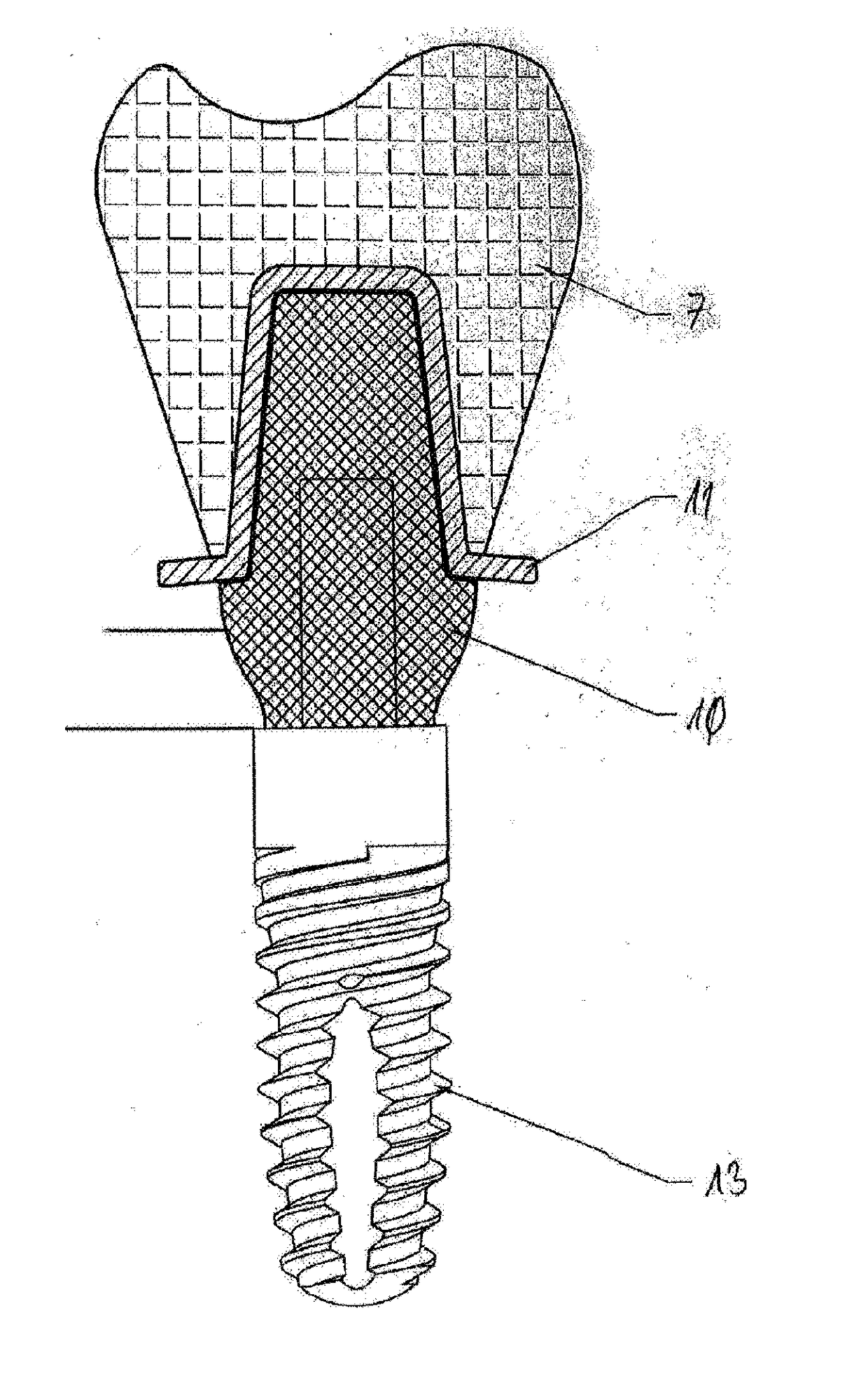
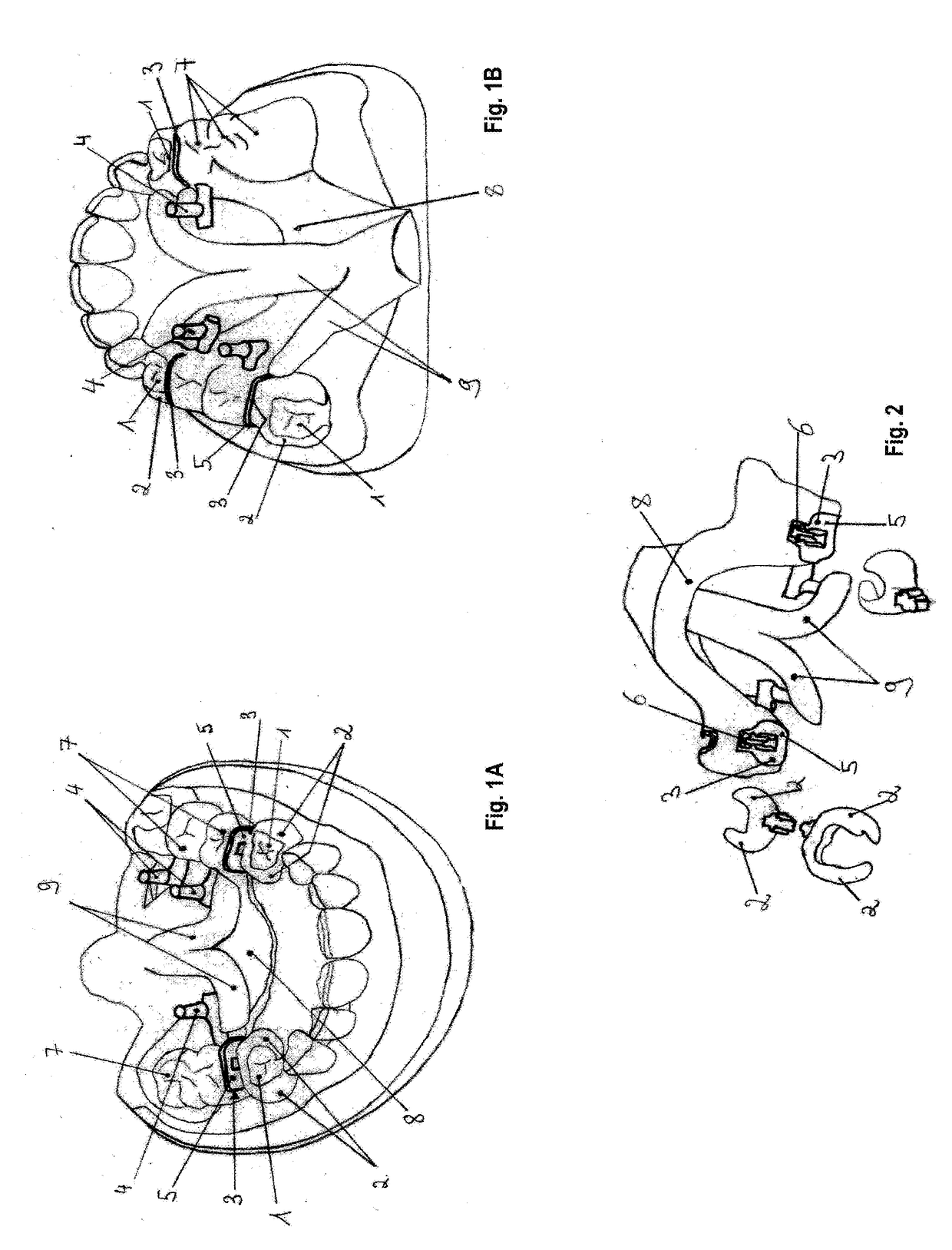
[0027]The dental prosthesis shown in the drawing is intended for inclusion in and attachment to existing residual dentition and / or at least one implant. Here, the individual teeth or implants form anchor elements for the dental prosthesis, as can be seen from FIGS. 1A and 1B.

[0028]For the preparation of this dental prosthesis, an imprint of the actual condition of the patient's jaw is first undertaken, and from this a master model and a working model are molded that then have the form shown by way of example in FIGS. 1A and 1B. In a manner not shown in detail in the drawing, the working model is adjustably fixed in a milling base and aligned with respect to the insertion direction in a milling machine or parallelometer.

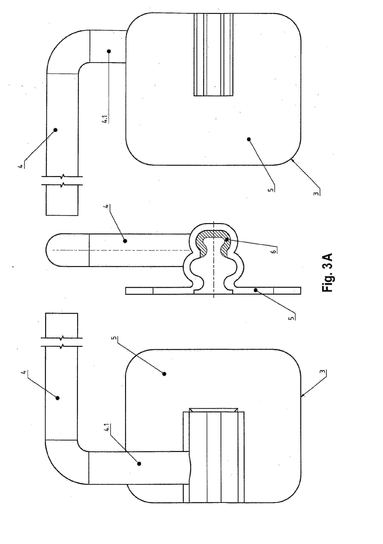
[0029]Then, adhesion surfaces 2 made from wax in the manner of wide-area brackets are molded onto the anchor elements 1, i.e. the formed anchoring elements for the dental prosthesis in the mouth of the patient (teeth, implants or the residue thereof). Depending on the...


PUM


Abstract

The method is used for making a dental prosthesis or for the adaptation of an existing dental prosthesis for the inclusion in and attachment to existing residual dentition and / or at least one implant. Here, individual teeth and / or implants and / or the remains thereof form the anchor elements for anchoring the dental prosthesis. First, an imprint of the actual condition of the jaw of the patient occurs, from which a master model and a working model are molded. Then, the working model is adjustably fixed in a milling base and aligned with respect to the insertion direction in a milling machine or parallelometer. Next, adhesion surfaces (2) made from wax in the manner of wide-area brackets, an adhesive bridge or the like are molded onto the molded anchor elements (1). Then a molded connecting part (3) with a permanently attached parallelization pin (4) and / or retention anchor element is waxed thereon after successful alignment with the insertion direction by means of the parallelization pins (4). Subsequently either the teeth (7) forming the dental prosthesis, the cast-model framework (8) and further necessary parts are modeled in wax, or the already an existing dental prosthesis are modeled on. Finally the model is provided with injection molding passages (9), and for this purpose each of the elements is worked on individually. Then, the model is embedded and boiled out for removing the wax, and that finally after insertion of the interchangeable matrix (duplicating matrix) into the molded connecting part (3) and surface treatment of the mold inner surfaces and the plaster mold, the mold is removed, followed by the removal of the dental prosthesis.

Description

CROSS REFERENCE TO RELATED APPLICATIONS[0001]This application claims the priority of German patent application 10 2014 019 519.8 filed 24 Dec. 2014.FIELD OF THE INVENTION[0002]The invention relates to a method of making a dental prosthesis or for the adaptation of an existing dental prosthesis for the inclusion in and attachment to existing residual dentition and / or at least one implant, where individual teeth and / or implants and / or the remains thereof form anchor elements for the dental prosthesis.BACKGROUND OF THE INVENTION[0003]Both from practice as well as from the literature, numerous and very different methods of this type are known that make it possible in very different manners to replace missing teeth in the mouth of a patient. Some of these methods are very time-consuming and costly, with the result that they at times fall out of consideration for individual patients on the basis of financial or time reasons.OBJECT OF THE INVENTION[0004]The object of the present invention ...

Claims


Application Information

Patent Timeline
Patent Type & Authority Applications(United States)
IPC IPC(8): A61C13/34A61C13/10A61C13/20A61C9/00A61C8/00A61C13/00
CPCA61C13/34A61C8/0001A61C13/0028A61C13/0003A61C8/0069A61C9/00A61C13/1003A61C13/206A61C5/73
Inventor BREHM, PETERWEBER, HEINER
Owner BREDENT
Learn More