
Bottom-Handled Bag Having Integral Ergonomic Handle Formed From Deflected Weld Line

Inactive Publication Date: 2017-08-10
BALDWIN BARLOW BARING INC
View PDF7 Cites 3 Cited by
  • Summary
  • Abstract
  • Description
  • Claims
  • Application Information

AI Technical Summary

Benefits of technology

The present invention is about improving the design of handles for bags made from thin-filmed plastic. The invention includes features to make the handle safer, stronger, and more durable. Additionally, it helps prevent the creation of flaps or debris that could interfere with the bag manufacturing process.

Problems solved by technology

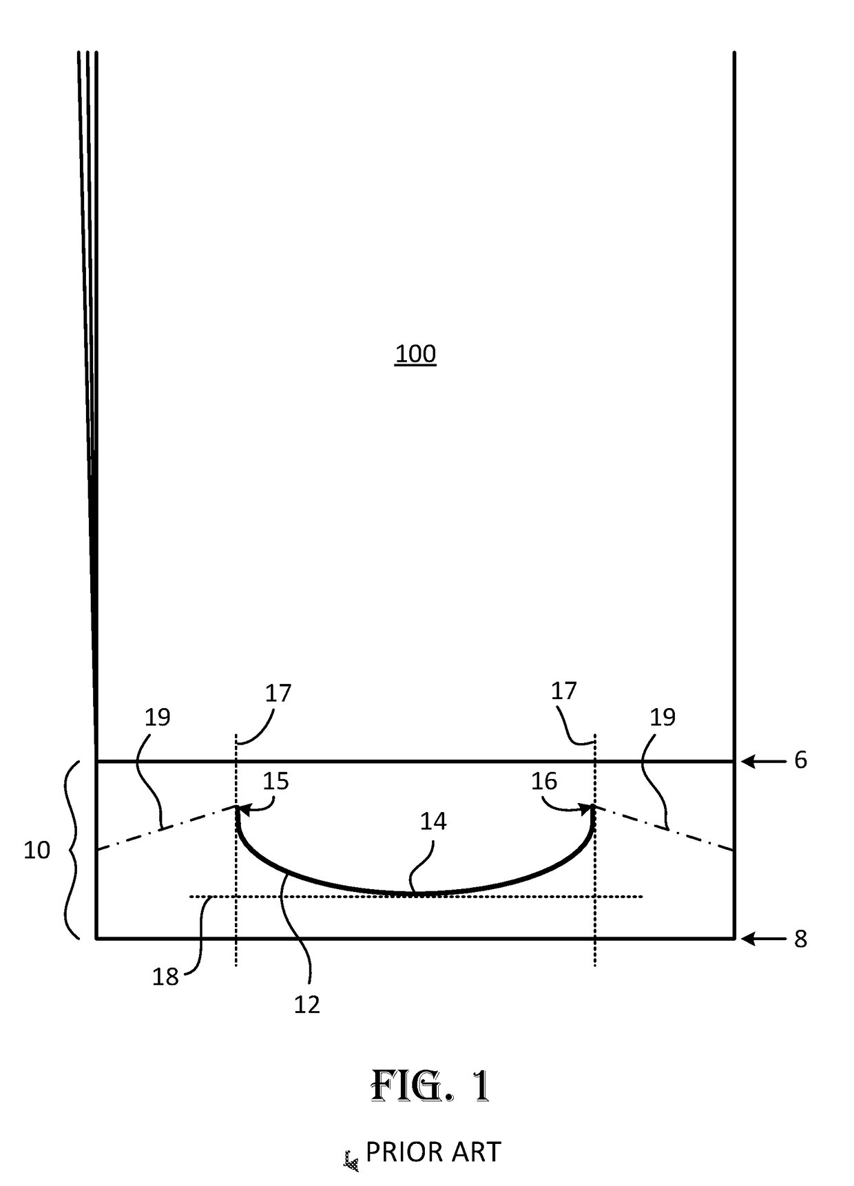
While Warr's approach seeks to improve the strength of the handle, it introduces new problems during manufacturing, particularly where the bags are formed from thin-film plastics.
The first new problem is that the hand insertion slit, which is cut through all layers of the plastic film, creates a flap of plastic that can be hazardous as the film is being run through various stages in its forming apparatus.
The flap tends to fold over and get caught in various components of machinery, causing tears and jamming.
The second problem occurs when the arcuate end portions of Warr's hand-insertion slit are formed as cut-outs.
The circular portions of film that are removed to form the cut-outs tend to disperse and jam the bag-making machinery, and also create debris that requires additional resources to remediate.

Method used


Image

  • Bottom-Handled Bag Having Integral Ergonomic Handle Formed From Deflected Weld Line
  • Bottom-Handled Bag Having Integral Ergonomic Handle Formed From Deflected Weld Line
  • Bottom-Handled Bag Having Integral Ergonomic Handle Formed From Deflected Weld Line

Examples


embodiment 300

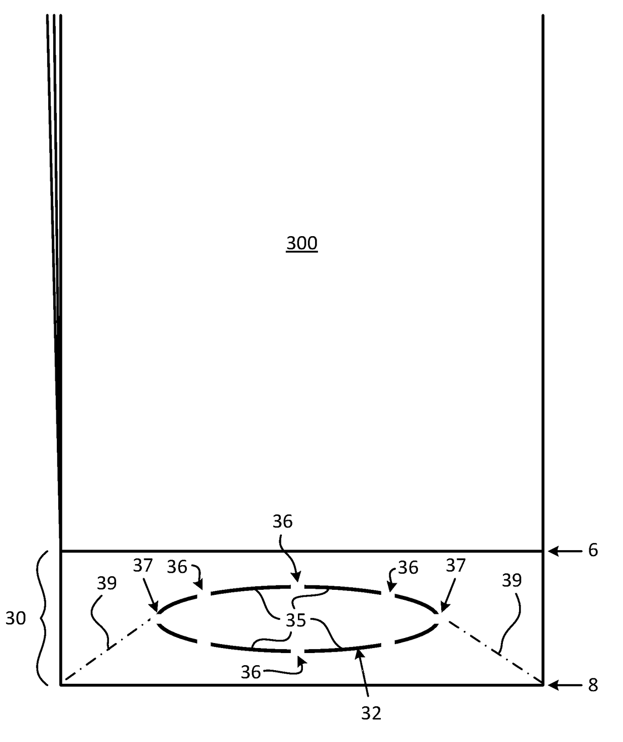
[0035]FIG. 3 shows an embodiment 300 of a bag according to the invention that has a lower handle area 30. The lower handle area 30 is bordered at top and bottom by transverse weld lines 6 and 8. Lower handle area 30 includes a deflected weld line 32 that forms an elliptical image. The deflected weld line 32 consists of multiple curved segments 35 that are each separated by a relatively short nonwelded segment or tag 36. Each curved segment 35 may be either a perforated weld line or a nonperforated weld line, or a combination of the two. The configuration of lower handle area 30 when tested caused diagonal tear lines 39 to run from a point 37 on a curved segment 35 at the right and left sides of the ellipse to the bottom transverse seal 8. This configuration, referred to herein as a “deflected circumference” weld line, exhibited the best failure rate and withstood loads of 70 lbs or greater across all gauges tested. See Table 1 below.

embodiment 400

[0036]FIG. 4 shows an alternative embodiment 400 of a bag according to the invention that has a lower handle area 40. The lower handle area 40 is bordered at top and bottom by transverse weld lines 6 and 8. Lower handle area 40 includes a deflected weld line 42 that forms an allantoidal or “sausage-shaped” image. The deflected weld line 42 consists of multiple curved segments 45 that are each separated by a relatively short nonwelded segment or tag 46. Each curved segment 45 may be either a perforated weld line or a nonperforated weld line, or a combination of the two. This configuration is another type of “deflected circumference” weld line. Load test results for lower handle area 40 are similar to those listed for lower handle area 30. The dashed lines 49 show the direction of tear from a point 47 to a corner of the bag when the handle area 40 is subjected to loading as described herein for testing conducted on other embodiments. The configuration of lower handle area 40 exhibits ...


PUM


Abstract

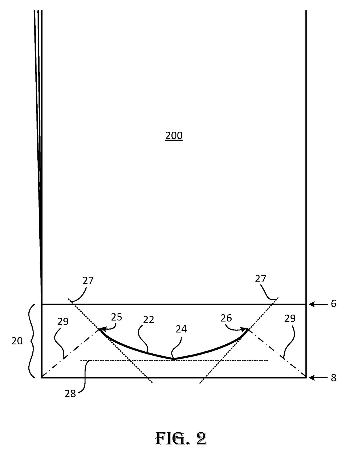
A handle body is formed in a lower end of a bag between a transverse bottom seal and an intermediate handle seal. The handle body has a deflected weld line having a midpoint and end points, and is nearest to the transverse bottom seal at the midpoint. The deflected weld line is arranged so that a line tangent to the deflected weld line at either end point defines an angle greater than or less than 90 degrees with respect to a second line running transversely through the midpoint. Between the midpoint and the end points, the deflected weld line can include different combinations of perforated, nonperforated, welded, and nonwelded line segments.

Description

RELATED APPLICATIONS[0001]This application claims the benefit of U.S. Provisional Application 62 / 292,290 which was filed on Feb. 6, 2016 and which is fully incorporated herein by reference.BACKGROUND OF THE INVENTION[0002]Field of the Invention[0003]The present invention relates to handle designs for bags such as plastic trash bags. More specifically, the invention relates to forming integral ergonomically safe handles within a handle area defined at the bottom end of a bag.[0004]Description of Related Art[0005]Assignees of the present invention have designed ergonomic trash bags equipped with lower handles that help reduce workplace injuries. These bags are marketed as LiteLift® bags, and are described in U.S. Pat. No. 8,790,009 and U.S. patent application Ser. No. 13 / 601,924, the specifications of which are fully incorporated herein by reference. As described in these specifications, the ergonomic trash bag is constructed of plastic film. Typically, the bags are made from a contin...

Claims


Application Information

Patent Timeline
IPC IPC(8): B65D33/08B65F1/14B65F1/00
CPCB65D33/08B65F1/14B65F1/0006B65F1/1468
Inventor SALE, MARK D.SAVILLE, TARA J.PAULSON, JAY B.
Owner BALDWIN BARLOW BARING INC
Learn More