Weather resistant pin lock

a pin lock and weather-resistant technology, applied in the field of pin locks, can solve the problems of early pin locks being prone to weather-related failure, corrosion, water penetration, locks are prone to freezing, etc., and achieve the effect of reducing water ingress

Inactive Publication Date: 2017-08-10
2603701 ONTARIO INC
View PDF7 Cites 1 Cited by
  • Summary
  • Abstract
  • Description
  • Claims
  • Application Information

AI Technical Summary

Benefits of technology

[0028]In some other aspects, the drainway may define a pathway for water to flow outwardly from the interior of the shell, the interior of the rotatable core, the access door, and an outer face ring surrounding the keyway. In some aspects, a water resistant seal is provided at the proximate end between the outer face ring and the shell or at the distal end to inhibit water ingress between the rotatable core and the shell. Preferably, the pin lock includes water resistant seals at the proximate end and the distal end to minimize water ingress.

Problems solved by technology

Earlier pin locks are prone to weather related failure, corrosion, water penetration and other weather related problems.
When this lock design is installed in locations which are exposed to outdoor weather conditions, there are a number of potential weather related issues.
By way of example, when installed in outdoor locations, such locks are prone to freezing particularly during weather conditions including temperature changes from rain to freezing rain or snow.
Water may pool at the lower pivot point which in turn may freeze and hinder movement of the dust cover.
Under these circumstances, water may freeze and render the lock inoperable.
Deformation of the dust cover may prevent the dust cover from subsequently operating correctly and it may become necessary to replace the prior art pin lock.
Prior art locks may also be prone to corrosion or other water / ice related damage because of water penetration and accumulation within those locks.

Method used


Image

  • Weather resistant pin lock
  • Weather resistant pin lock
  • Weather resistant pin lock

Examples


Embodiment Construction

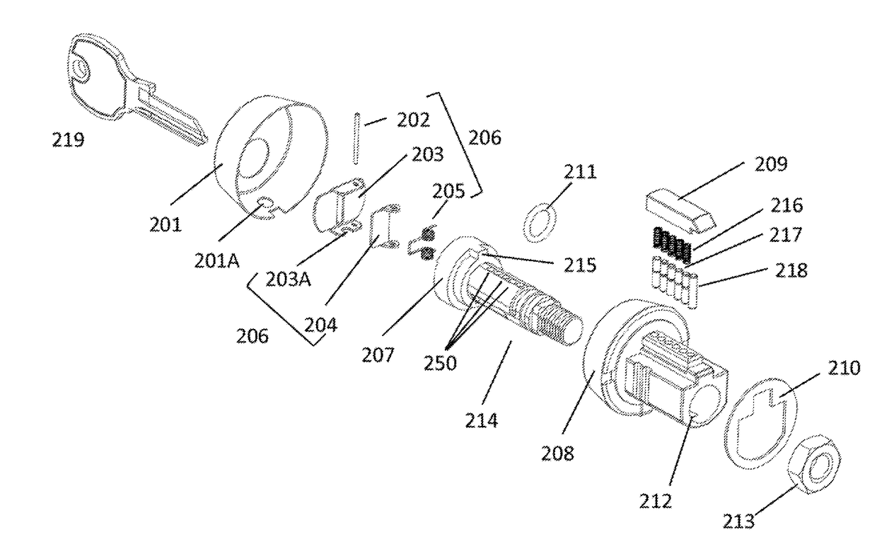
[0044]A preferred embodiment of the invention is described below having regard to the preferred embodiment as illustrated in FIGS. 4, 5A-5C, and 6A-6C. For applications in which the pin lock of the present invention will be used in retrofit installations, the shell assembly will be configured to match the existing furniture cut-out representing the available space for installation of the replacement lock. In this example, the profile of cylinder 101 is shown as 213 in FIG. 7. It is preferred that the shape of cylinder 101 is designed to match the existing profile in the furniture so that the lock can be retrofitted into existing furniture, for example, a storage structure having at least one locking compartment.

[0045]With reference to FIGS. 4 and 6C, the preferred pin lock of the present invention includes a shell configured as a generally U-shaped cylinder 208 which defines a chamber housing rotatable core 207, preferably made from stainless steel. The shell head 401 of the shell 2...


PUM


Abstract

A weather resistant pin lock with an elongated body, defining a longitudinal axis includes a shell housing a rotatable core having a keyway. An elevated pinway projects upwardly from the shell to define a linear array of pin slots containing a set of lock pins. A hood is fastened to the pinway to hold the lock pins in the pin slots and to provide a water resistant barrier. A drainway provides a channel for water to flow outwardly from the interior of the shell, the rotatable core and the keyway within the core, to a drain below the pin lock. At the proximate end, an access door rotates adjacent the keyway at an elevated position, to provide a gap along the bottom edge of the access door.

Description

BACKGROUND[0001]Field[0002]The present invention relates to pin locks and to a method of providing weather resistant features to the pin locks, which are desirable for outdoor use.[0003]Description of the Related Art[0004]Earlier pin locks are prone to weather related failure, corrosion, water penetration and other weather related problems. U.S. patent application Ser. No. 12 / 004,856 filed on Dec. 21, 2007 and published under publication number 2008 / 0276666 is an example of one such available pin lock.[0005]See FIGS. 1-3 and 7 of the present application which illustrate the features of one example of a prior art pin lock used in mailboxes including outdoor mailbox applications. When this lock design is installed in locations which are exposed to outdoor weather conditions, there are a number of potential weather related issues.[0006]By way of example, when installed in outdoor locations, such locks are prone to freezing particularly during weather conditions including temperature ch...

Claims


Application Information

Patent Timeline
Patent Type & Authority Applications(United States)
IPC IPC(8): E05B27/00E05B17/00E05B15/16E05B65/44E05B17/14E05B17/18
CPCE05B27/0003E05B17/142E05B17/002E05B15/16E05B65/44E05B17/183E05B17/181E05C3/042E05B29/00E05B63/0056E05B65/02E05B65/52E05Y2900/602
Inventor MCLEOD, JOHNSABELLI, TONINO
Owner 2603701 ONTARIO INC
Why Eureka
Try Eureka