Article Transport Facility

a technology for transporting facilities and articles, applied in the direction of mechanical conveyors, conveyors, railway signalling and safety, etc., can solve the problems of lowering the transport efficiency of the entire facility, and achieve the effect of improving the transport efficiency

Active Publication Date: 2017-08-10
DAIFUKU CO LTD
View PDF0 Cites 4 Cited by
  • Summary
  • Abstract
  • Description
  • Claims
  • Application Information

AI Technical Summary

Benefits of technology

[0012]In other words, when an article transport vehicle enters the managed area, the travel control of the article transport vehicle that entered the managed area is performed to allow and cause it to travel in the selected path if another article transport vehicle does not exist in the selected path, even if another article transport veh...

Problems solved by technology

However, causing the article transport vehicles to wait in the manag...

Method used


Image

  • Article Transport Facility
  • Article Transport Facility
  • Article Transport Facility

Examples


Embodiment Construction

[0026]Embodiments of an article transport facility in accordance with the present invention are described next with reference to the drawings.

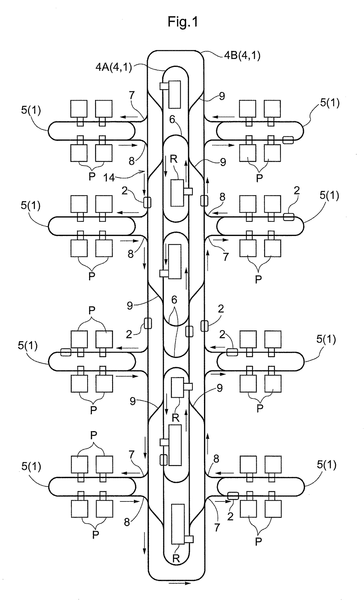
[0027]As shown in FIG. 1, the article transport facility includes article transport vehicles 2 each configured to travel along travel paths 1 to transport articles, and a pair of right and left travel rails 3 (which are sometimes referred to hereinafter simply as travel rails 3) installed along each of the travel paths1. Note that, in the present embodiment, each of the articles to be transported is a FOUP (Front Opening Unified Pod) for holding one or more semiconductor substrates. Each article transport vehicle 2 transports FOUPs, one FOUP at a time, by traveling on the travel rails 3 which are suspended from and supported by the ceiling.

[0028]The travel paths 1 include two primary paths 4 and a plurality of secondary paths 5 each of which extends by way of, or adjacent, a plurality of article processors P (i.e. devices for performing one or...


PUM


Abstract

A controller performs a stop control if a first detector detects that an article transport vehicle traveling in a first path entered a managed area, and a second detector or a third detector detects that another article transport vehicle exists in a selected path. And the controller performs a travel control if the first detector detects that an article transport vehicle traveling in a first path entered the managed area, and presence of another article transport vehicle is not detected in the selected path by the second detector or the third detector.

Description

CROSS-REFERENCE TO RELATED APPLICATION[0001]This application claims priority to Japanese Patent Application No. 2016-023764 filed Feb. 10, 2016, the disclosure of which is hereby incorporated in its entirety by reference.FIELD OF THE INVENTION[0002]The present invention relates to an article transport facility comprising an article transport vehicle configured to travel along travel paths to transport an article, a controller for controlling the article transport vehicle, wherein the travel paths include a first path extending from outside a managed area to a branching portion located inside the managed area, a second path and a third path which are two different paths, each of which extends from the branching portion to outside the managed area, wherein a downstream end of the first path, an upstream end of the second path, and an upstream end of the third path are connected together at the branching portion in the managed area, and wherein the controller is configured to select on...

Claims


Application Information

Patent Timeline
IPC IPC(8): H01L21/677B61L25/02B61L27/04
CPCH01L21/67715B61L27/04B61L2201/00H01L21/67724H01L21/67706B61L25/025B65G35/00B65G43/00H01L21/67727H01L21/6773H01L21/67733H01L21/67184H01L21/67196B65G43/08B65G49/061B61L23/14B65G2201/0297
Inventor KINUGAWA, TOMOTAKAOTSUKA, HIROSHI
Owner DAIFUKU CO LTD
Why Eureka
Try Eureka