Pneumatic Tire
Active Publication Date: 2017-08-17
SUMITOMO RUBBER IND LTD
View PDF8 Cites 7 Cited by
- Summary
- Abstract
- Description
- Claims
- Application Information
AI Technical Summary
Benefits of technology
[0003]The present invention was therefore made in view of the above, and a primary object of the present invention is to provide a pneumatic tire whi
Problems solved by technology
Further, simply providing the land region with sipes tends to reduce the rigidity of
Method used
View moreImage
Smart ImageViewing Examples
Examples
 PUM
 Abstract
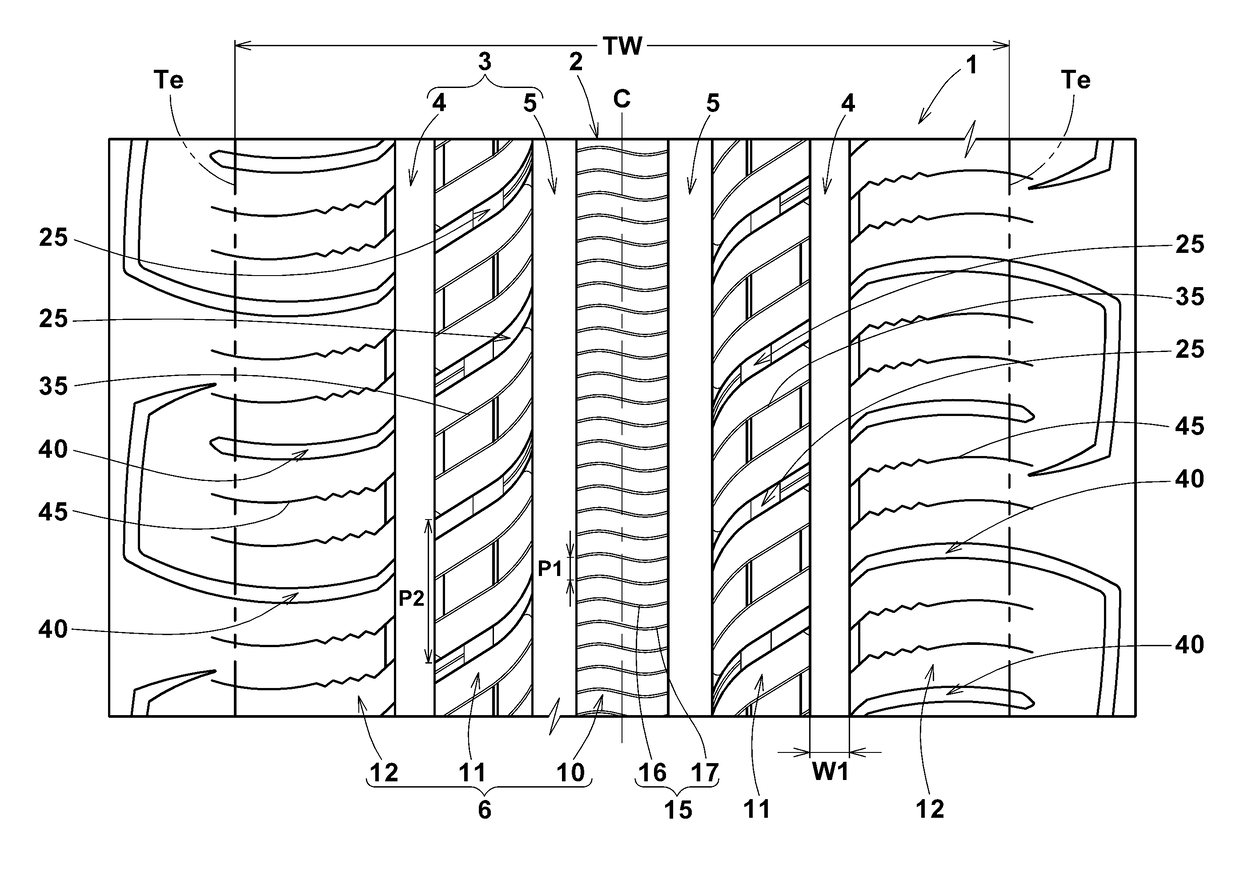
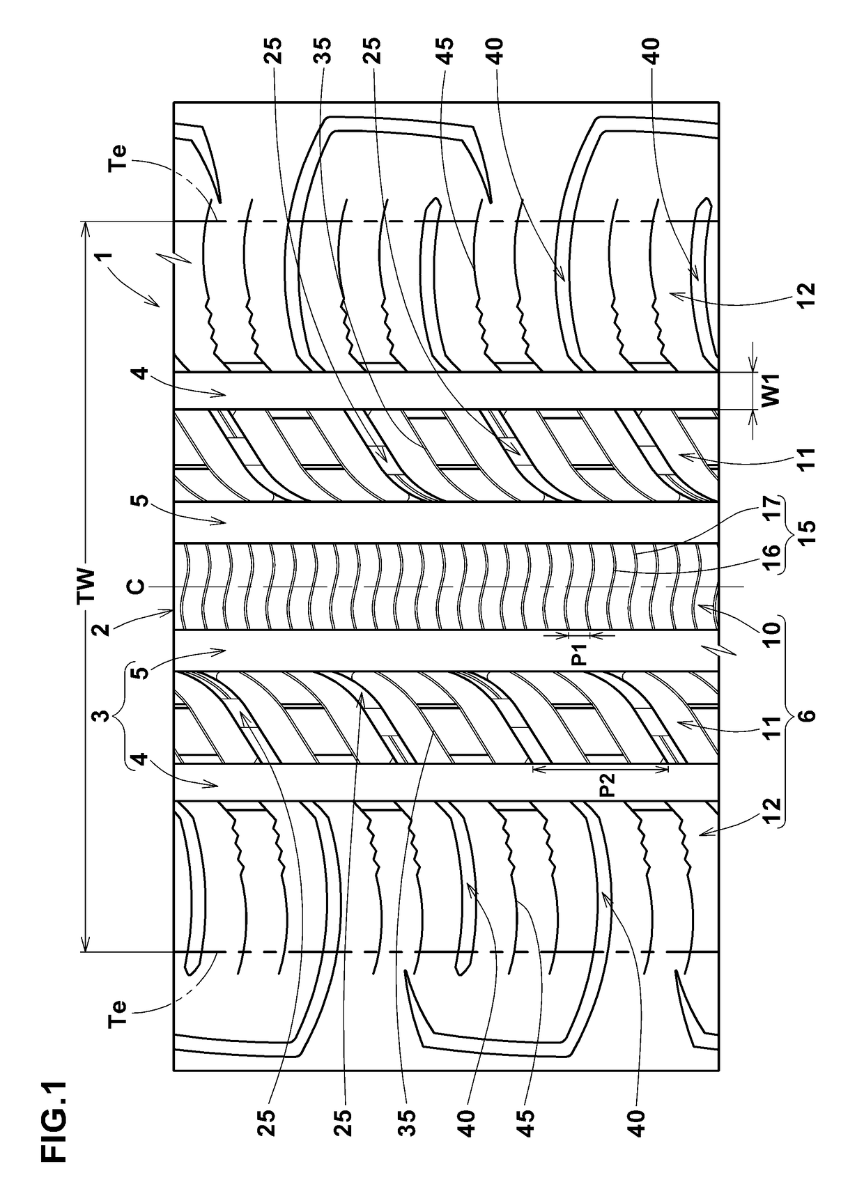
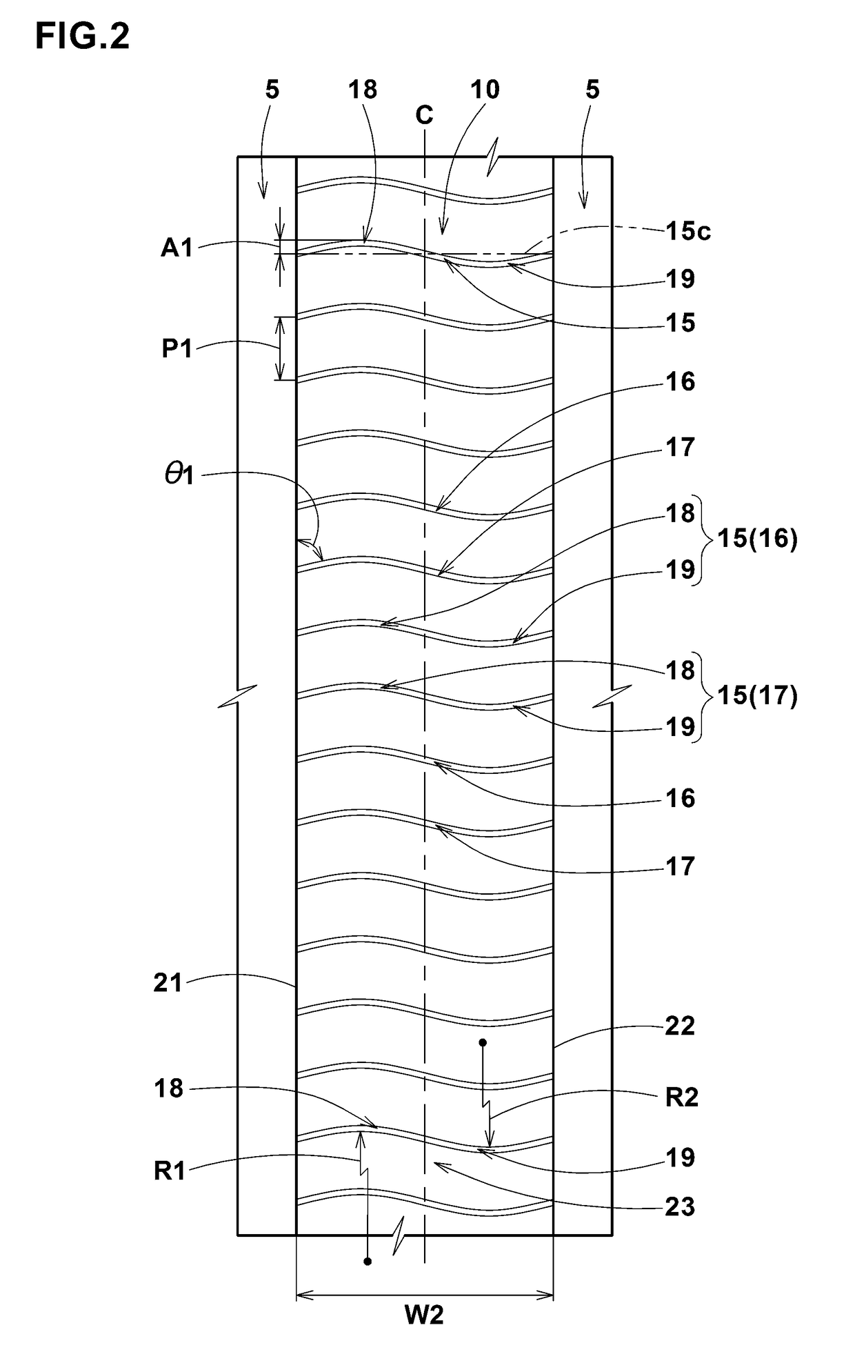
A pneumatic tire 1 is provided in a tread portion 2 with a circumferential land region 6 provided with transverse sipes 15 extending across the entire width of the circumferential land region. Each of the transverse sipes 15 comprises an arc-shaped first portion 18 convexed toward one side in the tire circumferential direction and an arc-shaped second portion 19 convexed toward the other side in the tire circumferential direction and connected with the first portion 18 so as to have a wavy configuration. The transverse sipes 15 include a first transverse sipe 16 of which first portion 18 is deeper than the second portion 19 thereof, and a second transverse sipe 17 of which second portion 19 is deeper than the first portion 18 thereof.
Description
TECHNICAL FIELD[0001]The present invention relates to a pneumatic tire improved in both the steering stability on dry roads and the running performance on snowy / icy roads.BACKGROUND ART[0002]Japanese Patent Application Publication No. 2006-160055 discloses a pneumatic tire having land regions provided with straight sipes and L-shaped sipes in order to improve on-the-snow performance. such straight or L-shaped sipe exert its edge effect to increase a frictional force only in one specific direction or two specific directions. Further, simply providing the land region with sipes tends to reduce the rigidity of the land region, and thereby the steering stability on dry roads tends to deteriorate.SUMMARY OF THE INVENTION[0003]The present invention was therefore made in view of the above, and a primary object of the present invention is to provide a pneumatic tire which is improved in the steering stability on dry roads and running performance on snowy / icy roads by improving the configura...
Claims
Login to View More Application Information
Patent Timeline
 IPC IPC(8): B60C11/12B60C11/04
CPCB60C11/1263B60C11/04B60C2011/1213B60C11/1236B60C11/1204B60C11/12B60C11/13B60C11/1392B60C2011/0341B60C2011/0388B60C2011/1268
Inventor KANEMATSU, YOSHIAKI
Owner SUMITOMO RUBBER IND LTD
Features
- R&D
- Intellectual Property
- Life Sciences
- Materials
- Tech Scout
- Unparalleled Data Quality
- Higher Quality Content
- 60% Fewer Hallucinations
Learn More Browse by: Latest US Patents, China's latest patents, Technical Efficacy Thesaurus, Application Domain, Technology Topic, Popular Technical Reports.
© 2025 PatSnap. All rights reserved.Legal|Privacy policy|Modern Slavery Act Transparency Statement|Sitemap|About US| Contact US: help@patsnap.com


