Vehicle convoy control system and method

a control system and vehicle technology, applied in the direction of brake systems, locomotives, braking components, etc., can solve the problems of rail cars on the upward slope of the hill to move slower, cars on the downward slope of the hill to move faster, and unsatisfactory forces on the couplers of the rail cars

Active Publication Date: 2017-08-17
GE GLOBAL SOURCING LLC
View PDF7 Cites 31 Cited by
  • Summary
  • Abstract
  • Description
  • Claims
  • Application Information

AI Technical Summary

Benefits of technology

[0015]In one embodiment, a method (e.g., for determining operational settings for a vehicle system having two or more propulsion-generating vehicles coupled with each other by one or more non-propulsion generating vehicles) includes obtaining route data and vehicle data. The route data is representative of one or more grades of a route at one or more locations along the route that is to be traveled by the vehicle system. The vehicle data is representative of a size of the one or more non-propulsion generating vehicles disposed between the propulsion-generating vehicles. The method also includes calculating one or more estimated natural forces that are to be exerted on couplers connected with the one or more non-propulsion generating vehicles of the vehicle system at the one or more locations along the route. The one or more estimated natural forces are based on the size of the one or more non-propulsion generating vehicles and the one or more grades of the route at the one or more locations along the route. The method also includes determining asynchronous operational settings to be implemented by the two or more propulsion-generating vehicles at the one or more locations along the route. Implementing the asynchronous operational settings by the two or more propulsion-generating vehicles reduces one or more actual natural forces that are actually exerted on the couplers to forces that are smaller than the one or more estimated natural forces when the vehicle system travels over the one or more locations along the route.

Problems solved by technology

Using the same throttle or brake settings for multiple locomotives traveling over different grades and / or curvatures can result in undesirable forces on couplers of the rail cars that are located between the locomotives and / or undesirable movements of the rail cars.
For example, when cresting a hill, using the same throttle settings on all locomotives can cause the rail cars located at or near the apex of the hill to experience relatively large tensile forces, can cause the rail cars on the downward slope of the hill to move faster than and away from other rail cars at or near the apex, and / or can cause the rail cars on the upward slope of the hill to move slower than and away from the other rail cars at or near the apex.
These forces and / or movements can damage the couplers, cause the rail vehicle system to break apart, and / or generally degrade handling of the rail vehicle system as experienced by an operator of the rail vehicle system.
Some known vehicle systems do not individually control brakes of different vehicles.
Consequently, applying the brakes for some vehicles may be inappropriate but needed for other vehicles at the same time.
But, the process of repeatedly changing which trucks move the trailers and which trains include the different rail cars can result is significant delay and inefficient operation in moving cargo through the transportation systems.

Method used


Image

  • Vehicle convoy control system and method
  • Vehicle convoy control system and method
  • Vehicle convoy control system and method

Examples


Embodiment Construction

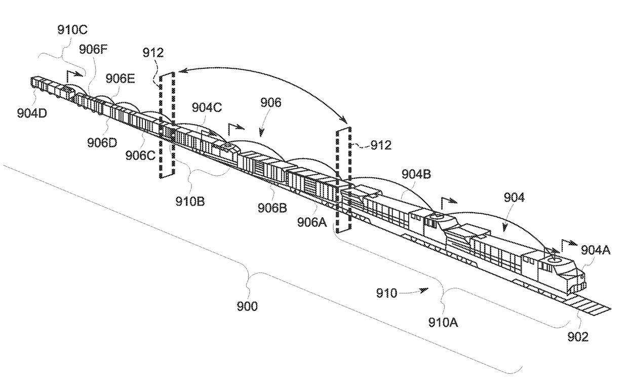
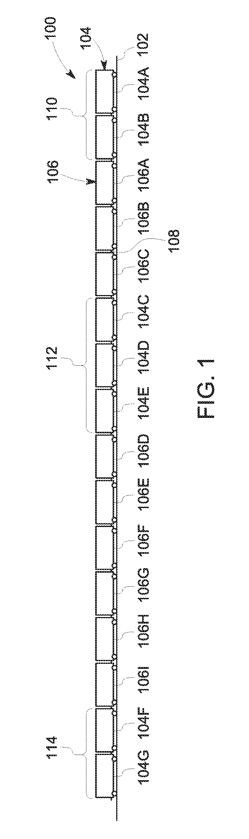
[0043]FIG. 1 illustrates a schematic diagram of one example of a vehicle system 100 traveling along a route 102. The vehicle system 100 includes several vehicles 104, 106 operably coupled with each other. The vehicles may be mechanically coupled with each other, such as by couplers 108. Alternatively, the vehicles may be coupled with each other without being mechanically coupled with each other. For example, the vehicles may be aerodynamically or fluidly coupled with each other when the vehicles travel sufficiently close to each other that the drag forces imparted on one or more of the vehicles (e.g., from air, wind, water, or the like), is reduced on one or more other vehicles. Marine vessels may be fluidly or aerodynamically coupled when the vessels travel close enough together such that the drag on one or more vessels from the water is reduced relative to the marine vessels traveling farther apart. Automobiles (e.g., trucks) may be fluidly or aerodynamically coupled when the auto...


PUM


Abstract

A control system identifies vehicle systems for combining into a larger convoy. Each the vehicle systems is formed from at least one propulsion-generating vehicle and at least one non-propulsion-generating vehicle. The control system directs the identified vehicle systems to couple with each other for travel as the convoy from a first location toward a different, second location. The control system directs a first vehicle system in the convoy to separate from the convoy and / or a second vehicle system to join the convoy by coupling with at least one of the vehicle systems in the convoy in an intermediate location between the first and second locations. The vehicles in each of the vehicle systems in the convoy remain connected during separation of the first vehicle system from the convoy and / or during joining of the second vehicle system to the convoy.

Description

CROSS-REFERENCE TO RELATED APPLICATIONS[0001]This application is a continuation-in-part of U.S. patent application Ser. No. 14 / 798,678, which was filed on 14 Jul. 2015 (the “'678 application”), which is a continuation-in-part of U.S. patent application Ser. No. 14 / 631,495 (now U.S. Pat. No. 9,453,735), which was filed on 25 Feb. 2015 (the “'495 application”), which is a continuation-in-part of U.S. patent application Ser. No. 14 / 319,885 (now U.S. Pat. No. 9,002,547, filed on 30 Jun. 2014 (the “'885 application”), which is a continuation-in-part of U.S. patent application Ser. No. 13 / 729,298 (now U.S. Pat. No. 8,838,302), filed on 28 Dec. 2012 (the “'298 application”). The entire disclosures of the '678 application, the '495 application, the '885 application, and the '298 application are incorporated herein by reference.FIELD[0002]Embodiments of the subject matter disclosed herein relate to controlling operations of vehicle systems.BACKGROUND[0003]Some known vehicle systems include m...

Claims


Application Information

Patent Timeline
Patent Type & Authority Applications(United States)
IPC IPC(8): B60T8/17B61L15/00B60T15/14B61L25/02B60T13/66B61L27/00B61L25/00
CPCB60T8/1705B61L27/0022B61L15/0072B61L25/00B61L2201/00B61L25/025B60T13/665B60T15/14B61L25/021Y02T90/16B61C17/12B60T8/171B60L15/2009B60L15/2045B60L15/38B61L3/006B61L3/008B61L15/0027B61L15/0081B60L2200/26B60L2240/642B60L2240/80B60L2270/12B60L2240/645B60T7/128B60T17/228G08G1/22Y02T10/72Y02T30/00B61L27/16B61L27/14B61G5/02
Inventor BROOKS, JAMES D.MATHEWS, HARRY KIRK
Owner GE GLOBAL SOURCING LLC
Why Eureka
Try Eureka