Coating device and coating method

Active Publication Date: 2017-08-24
HONDA MOTOR CO LTD
View PDF1 Cites 12 Cited by
  • Summary
  • Abstract
  • Description
  • Claims
  • Application Information

AI Technical Summary

Benefits of technology

The present invention is about a coating device that has a discharge nozzle group, which is made up of multiple discharge nozzles that are arranged and aligned. The objective of this invention is to reduce the variation in the amount of discharge that occurs in this group of nozzles. The patent text can be summarized as saying that this invention helps to create a coating device that can better control the amount of discharge that comes out of each nozzle, resulting in a more consistent and efficient coating process.

Problems solved by technology

In other words, in the coating device disclosed in patent document 1, the amount of discharge of the viscous material in the nozzle may be unstable.

Method used


Image

  • Coating device and coating method
  • Coating device and coating method
  • Coating device and coating method

Examples


Embodiment Construction

[0031]A first embodiment of the present invention will be described in detail below with reference to drawings.

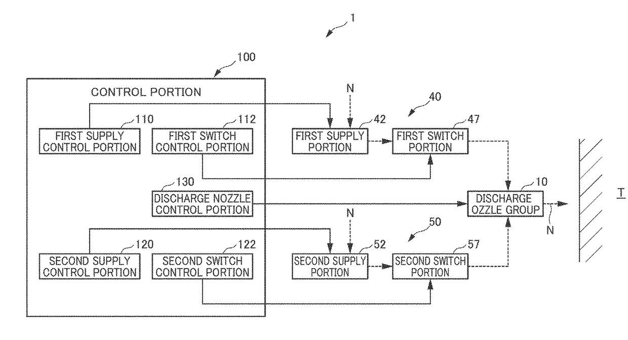
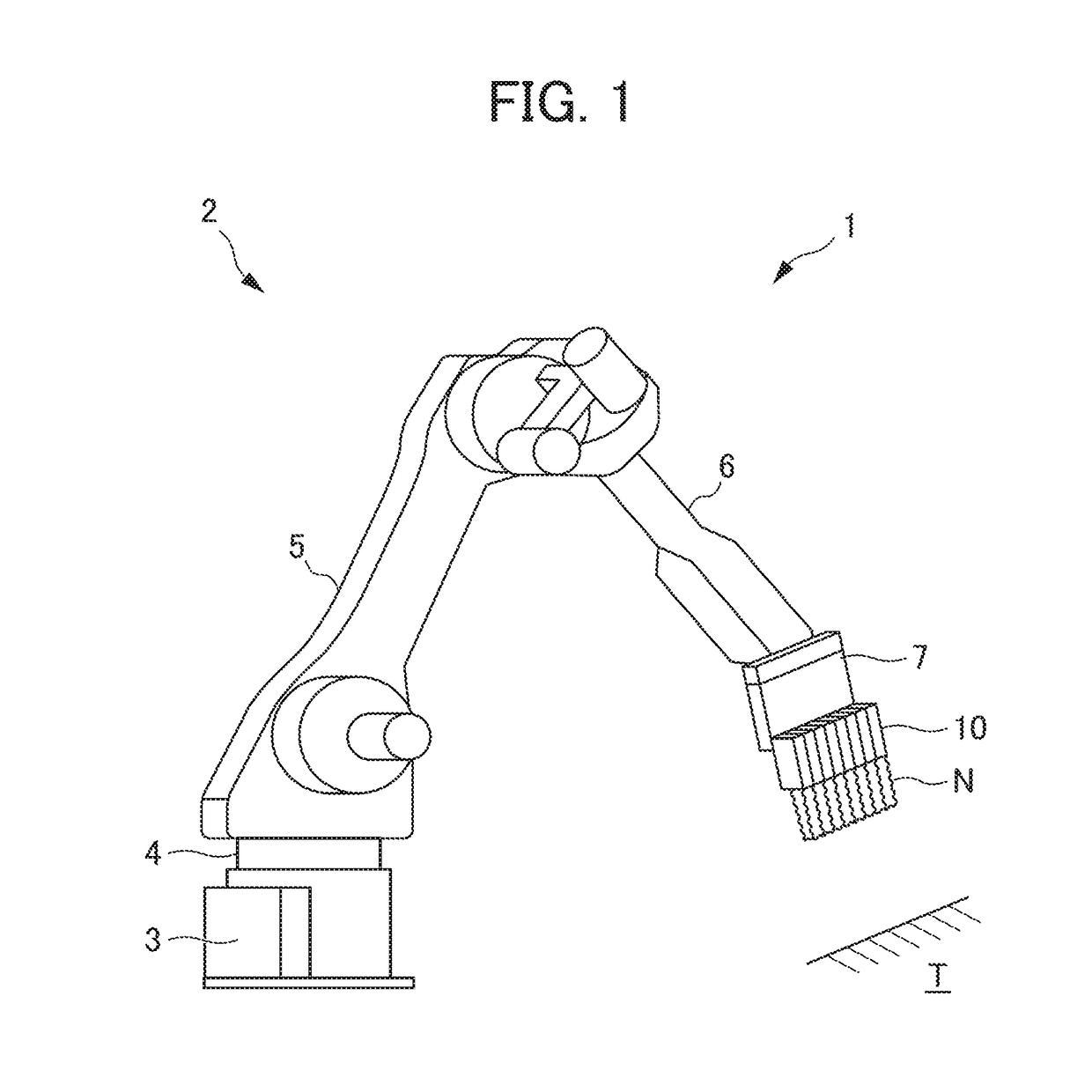
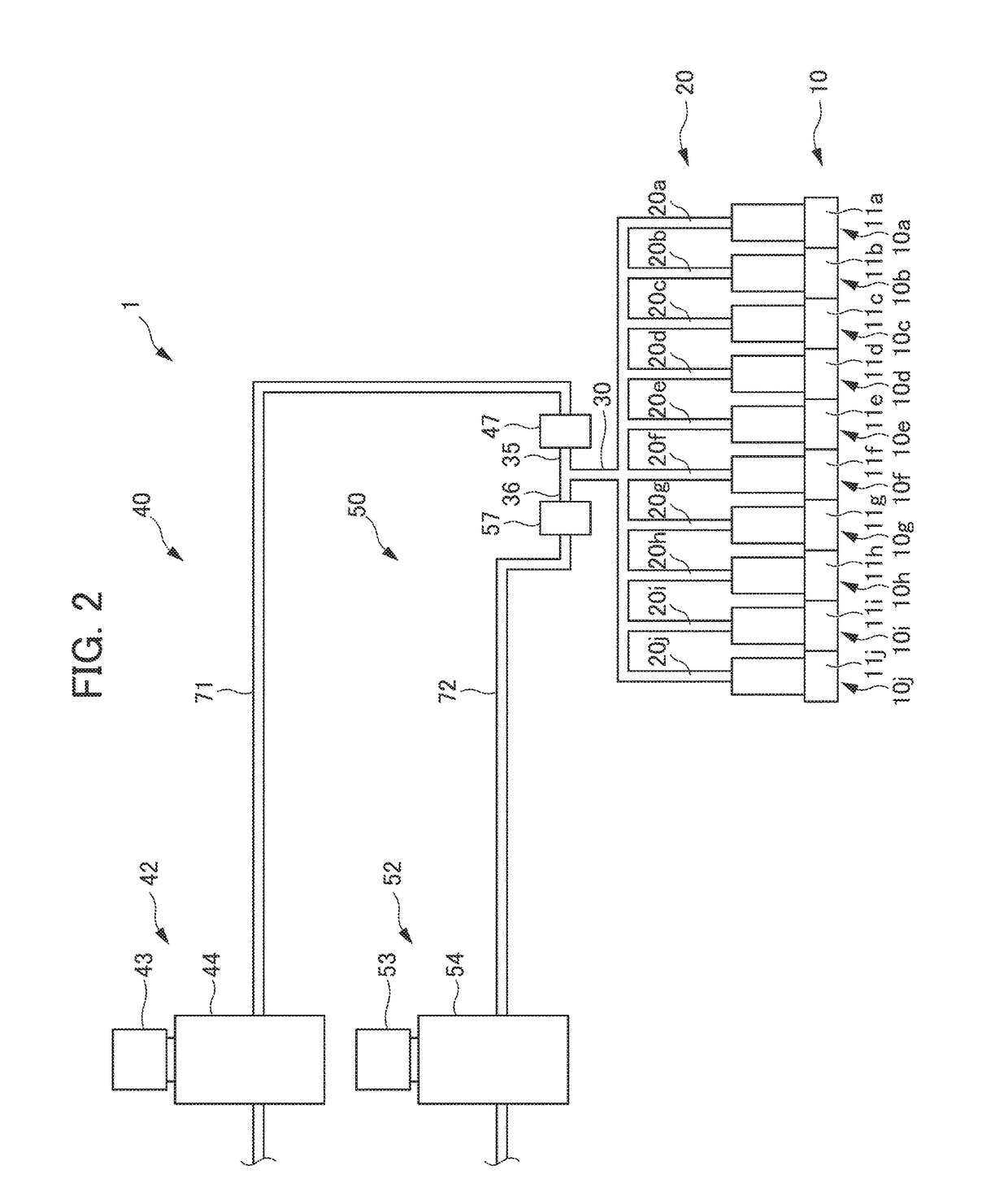
[0032]A coating device 1 in the embodiment will first be described with reference to FIGS. 1 to 4. FIG. 1 is a diagram showing the appearance of the coating device according to the embodiment of the present invention. FIG. 2 is a diagram showing the configuration of the coating device according to the embodiment of the present invention. FIG. 3 is a control block diagram of the coating device according to the embodiment of the present invention. FIG. 4(a) is a diagram showing a discharge state in a first time zone, FIG. 4(b) is a diagram showing a discharge state in a second time zone and FIG. 4(c) is a diagram showing a discharge state in a third time zone.

[0033]As shown in FIG. 1, the coating device 1 in the present embodiment is a device which coats a target T (for example, the body of an automobile) with a viscous material N (for example, a vibration damping material). ...


PUM


Abstract

The present invention has an object to provide a coating vice which can reduce variation in the amount of discharge in the discharge nozzle group. A coating device 1 includes: a first supply unit 40 and a second supply unit 50 which can supply a viscous material N to the discharge nozzle group 10; and a control portion 100 which stops, at the timing at which a first time zone is switched to a second time zone, the supply in the first supply unit 40, which makes the second supply unit 50 start the supply of the viscous material N to the discharge nozzle group 10 at a second flow rate and which makes, in a second time zone, the first supply unit 40 start the preparation of the viscous material necessary in any one of a third time zone and the subsequent time zones.

Description

[0001]This application is based on and claims the benefit of priority from Japanese Patent Application No. 2016-03173, filed on 23 Feb. 2016, the content of which is incorporated herein by reference.BACKGROUND OF THE INVENTION[0002]Field of the Invention[0003]The present invention relates to a coating device which applies a viscous material, and a coating method using the coating device.[0004]Related Art[0005]Conventionally, in the body of an automobile, a vibration damping member which has vibration-proof and sound-proof functions is arranged in order to, for example, reduce engine transmission sound to the interior of the automobile. For example, the vibration damping member, which is coated with a viscous material, is arranged (formed) within the body of the automobile.[0006]Here, when the shape of a coated region is complicated, it is necessary to apply the viscous material while reciprocating a nozzle with a narrow coating width a plurality of times, with the result that it dis...

Claims


Application Information

Patent Timeline
IPC IPC(8): B05D1/02B05B1/30
CPCB05B1/30B05D1/02B05B1/14B05B13/0431
Inventor KAWABE, GAKUMURAKAMI, SHINYA
Owner HONDA MOTOR CO LTD
Why Eureka
Try Eureka