Strobe device

Inactive Publication Date: 2014-07-03
PANASONIC INTELLECTUAL PROPERTY MANAGEMENT CO LTD
View PDF4 Cites 2 Cited by
  • Summary
  • Abstract
  • Description
  • Claims
  • Application Information

AI Technical Summary

Benefits of technology

The patent text describes a configuration for a strobe device that makes it more compact and thin than traditional configurations. This configuration also ensures a stable discharge path for the flash discharge tube, which reduces variations in the amount of light emitted and provides a consistent irradiation of the subject.

Problems solved by technology

This causes the joint of the lead wire to develop heat and degrade due to the resistance component of the joint.
Another problem is that the trigger coil generally has a large volume, which prevents the strobe devices from being compact.
In the strobe device of Patent Literature 1, however, the thin-film transparent electrode formed on the surface of the flash discharge tube undesirably absorbs the light emitted from the flash discharge tube.

Method used


Image

  • Strobe device
  • Strobe device
  • Strobe device

Examples


Embodiment Construction

[0021]A strobe device according to an exemplary embodiment of the present invention will now be described with reference to drawings. Note that the present invention is not limited to the following exemplary embodiment.

Exemplary Embodiment

[0022]The strobe device according to the exemplary embodiment of the present invention will now be described with reference to FIGS. 1 to 7B.

[0023]First, the schematic configuration of the strobe device of the exemplary embodiment of the present invention will be described with reference to FIGS. 1 to 3.

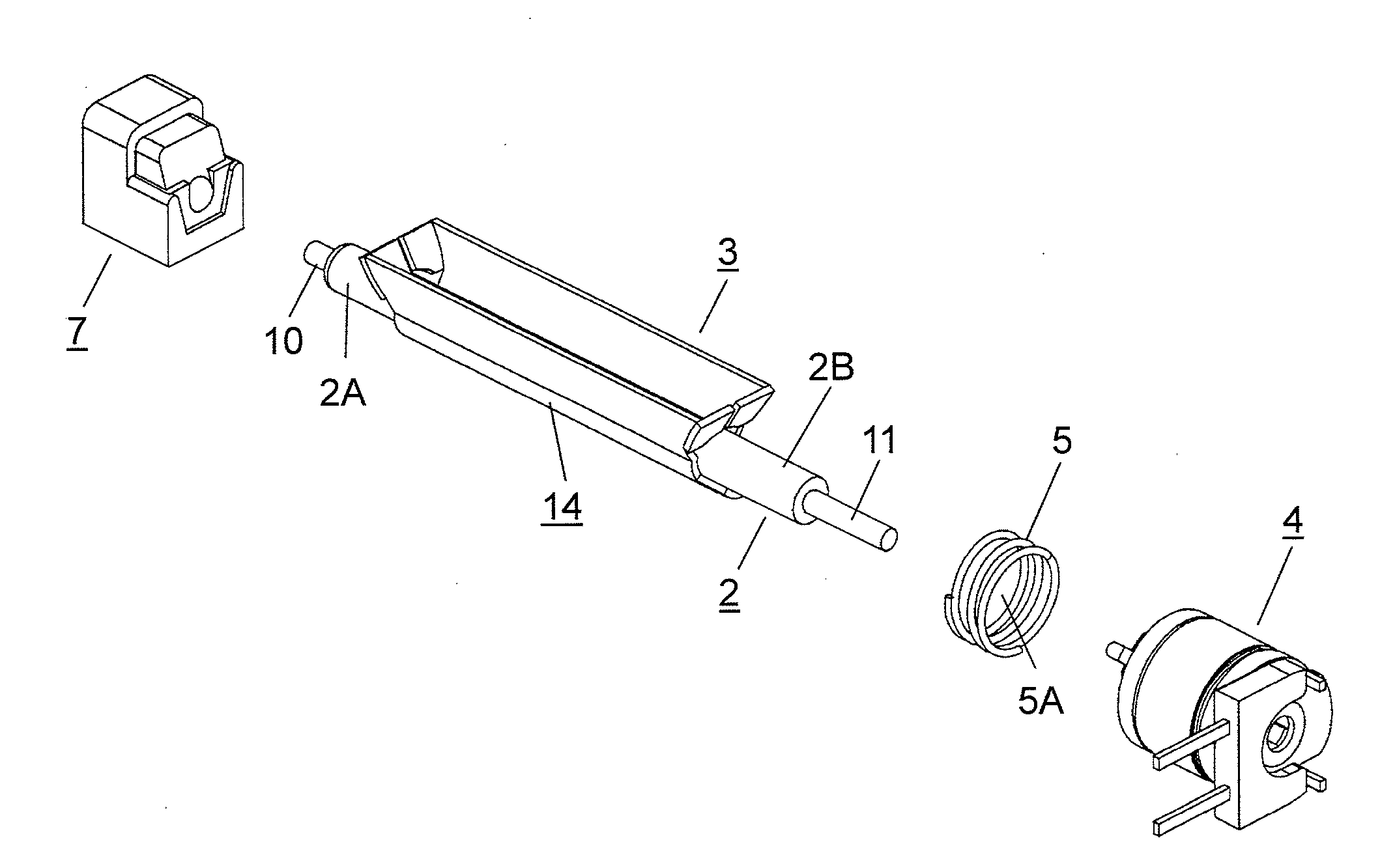
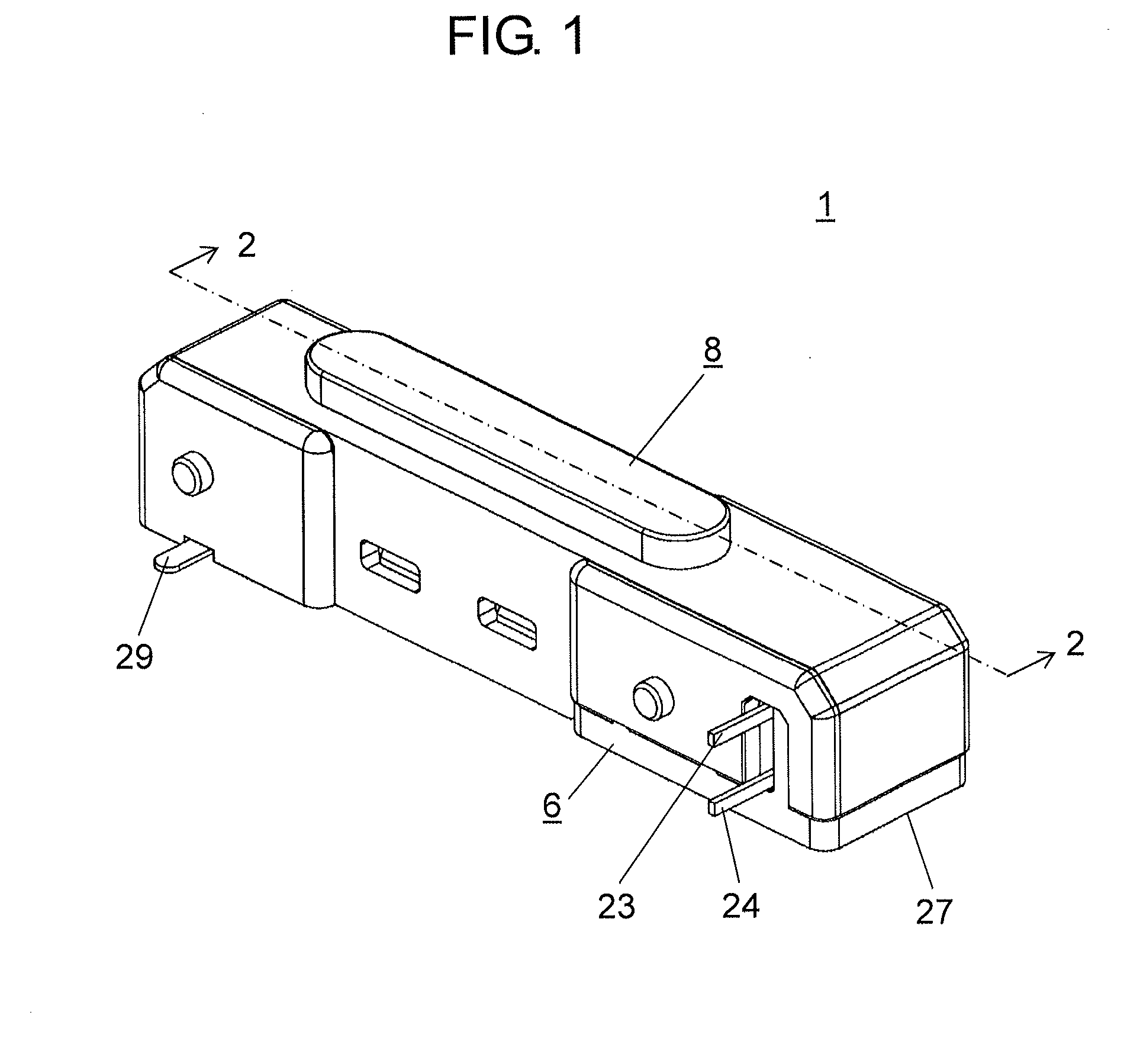
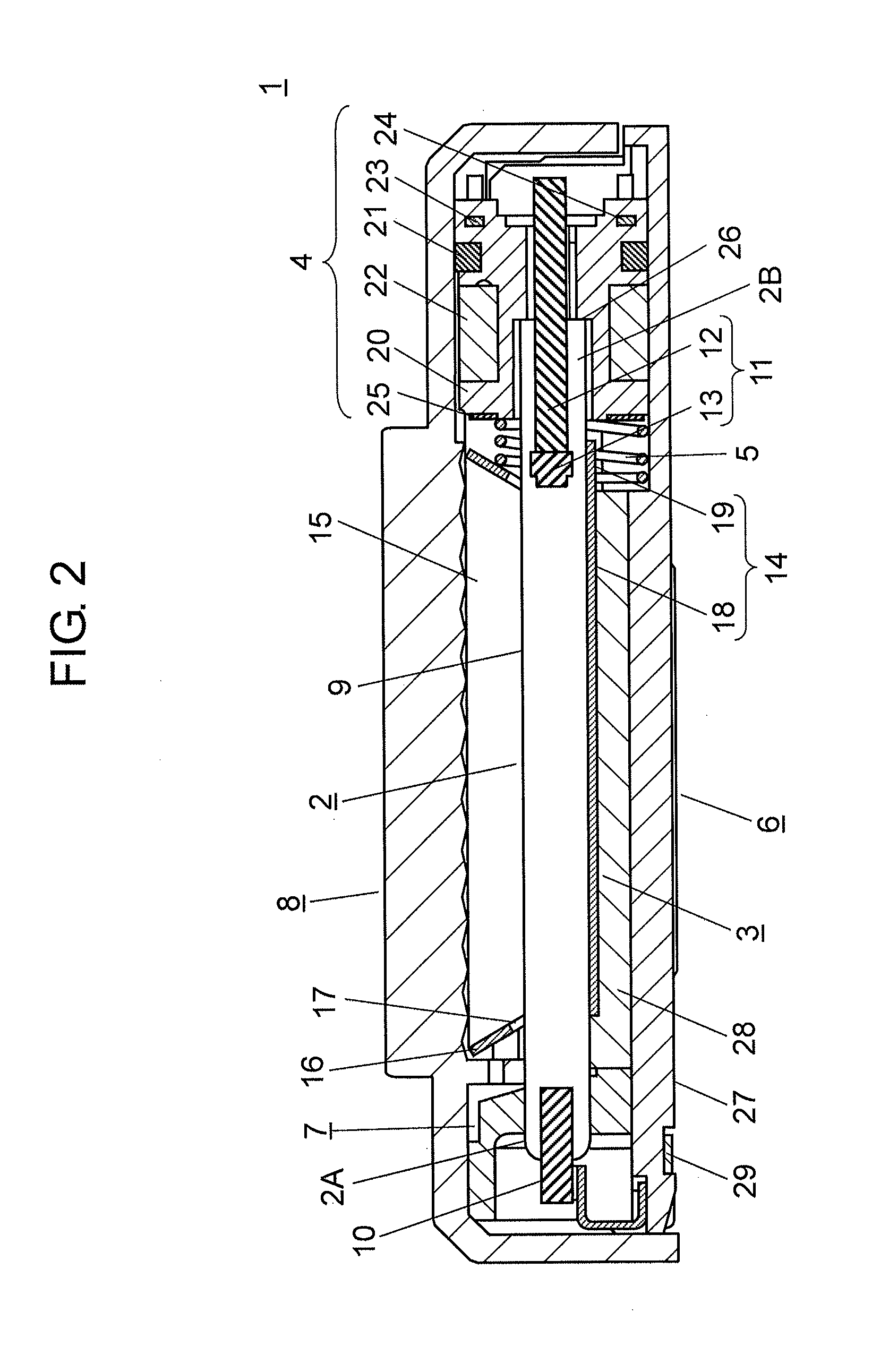
[0024]FIG. 1 is a perspective view of the strobe device according to the exemplary embodiment. FIG. 2 is a sectional view of the strobe device according to the exemplary embodiment taken along line 2-2 of FIG. 1. FIG. 3 is an exploded perspective view of the strobe device according to the exemplary embodiment.

[0025]As shown in FIG. 1, strobe device 1 of the exemplary embodiment includes base 6 which has body 27 including anode terminal 29, and optic...


PUM


Abstract

A strobe device having small variations in the amount of light includes the following components: a flash discharge tube having an anode on one side and a cathode on the other side, the cathode having a metal sintered body at an end thereof; a conductive reflector composing an external trigger electrode, and storing a part of the flash discharge tube; and a trigger coil having a primary winding and a secondary winding around a hollow core. A portion of the cathode of the flash discharge tube not including the metal sintered body is inserted into the core of the trigger coil. The reflector, which is connected to the secondary winding of the trigger coil, has a bottom in contact with the outer peripheral surface of the flash discharge tube in such a manner as to cover at least the region extending from the anode to the cathode and the metal sintered body.

Description

[0001]This application is a U.S. National Phase Application of PCT International Application PCT / JP2012 / 004974.TECHNICAL FIELD[0002]The present invention relates to a strobe device used for taking pictures or other purposes.BACKGROUND ART[0003]Conventional well-known strobe devices include the following components: a flash discharge tube having an anode on one side and a cathode on the other side which includes a metal sintered body at an end thereof; a reflector storing a part of the flash discharge tube; and a trigger coil having a cylindrical core and primary winding and secondary winding wound around the core.[0004]In the above strobe devices, the flash discharge tube has a conductive thin-film transparent electrode formed on its surface, and the secondary winding of the trigger coil is connected to the thin-film transparent electrode of the flash discharge tube. This configuration allows the thin-film transparent electrode to function as an external trigger electrode, thereby i...

Claims


Application Information

Patent Timeline
IPC IPC(8): F21V23/02G03B15/02F21V7/00
CPCF21V23/02G03B15/02F21V7/005G03B2215/0578G03B2215/0532G03B15/03
Inventor KONDO, TAKAOTAKASAKI, KOJIMAKI, TOSHINORIMURAI, TOSHIAKI
Owner PANASONIC INTELLECTUAL PROPERTY MANAGEMENT CO LTD
Why Eureka
Try Eureka