Constant temperature liquid circulating device and method of controlling temperature in the device

a technology of constant temperature liquid and circulating liquid, which is applied in the direction of domestic cooling devices, heating types, instruments, etc., can solve the problems of excessive energy required, reduce the variation in reduce the variation in the temperature of the external device itself, and reduce the variation in the temperature of the circulating liquid.

Active Publication Date: 2007-04-05
SMC CORP
View PDF2 Cites 24 Cited by
  • Summary
  • Abstract
  • Description
  • Claims
  • Application Information

AI Technical Summary

Benefits of technology

[0022] In the method of controlling the temperature by the constant temperature liquid circulating device configured as described including: performing a composite control in which a function to vary the flow amount of the circulating liquid flowing in the external device corresponding to the heat load is added to the related art in which the heat load of the external device is controlled only with the temperature of the circulating device and, more specifically, detecting the discharge temperature (T1) and the return temperature (T2) of the circulating liquid by the temperature sensors provided in the conduit of the constant temperature liquid circulating device, calculating a heat load of the external device from the temperature difference between the discharge and return temperature (T1, T2) of the circulating liquid detected by the both temperature sensors and the flow amount of circulating liquid detected by the flow amount sensor, controlling the temperature of the circulating liquid corresponding to the heat load when the heat load is smaller than a certain preset value, and increasing or reducing the flow amount or the pressure of the circulating liquid to the heat load portion of the eternal device according to the heat load in addition to the temperature control of the circulating liquid when the heat load is larger than the certain preset value. Therefore, the variation in temperature of the circulating liquid can be reduced to a small level and the variation in temperature of the external device itself in association therewith can be reduced and stabilized.
[0023] According to the constant temperature liquid circulating device and the method of controlling the temperature with the same, since not only the temperature, but also the flow amount of the circulating liquid are varied corresponding to the heat load of the external device, the width of temperature variation of the circulating liquid due to the variation in heat load can be reduced, and the variation in temperature of the external device itself is also reduced, so that the performance is stabilized, the response with respect to the temperature variation of the circulating liquid is improved, and the stability of the temperature can be improved.
[0024] Since the amount of variation in cooling and heating of the temperature controlling liquid and the circulating liquid or the like in the constant temperature liquid circulating device is reduced, energy saving is achieved.

Problems solved by technology

Since all the circulating liquid in the tank 41 is lowered / raised within a wide temperature width, excessive energy is required.

Method used


Image

  • Constant temperature liquid circulating device and method of controlling temperature in the device
  • Constant temperature liquid circulating device and method of controlling temperature in the device
  • Constant temperature liquid circulating device and method of controlling temperature in the device

Examples


first embodiment

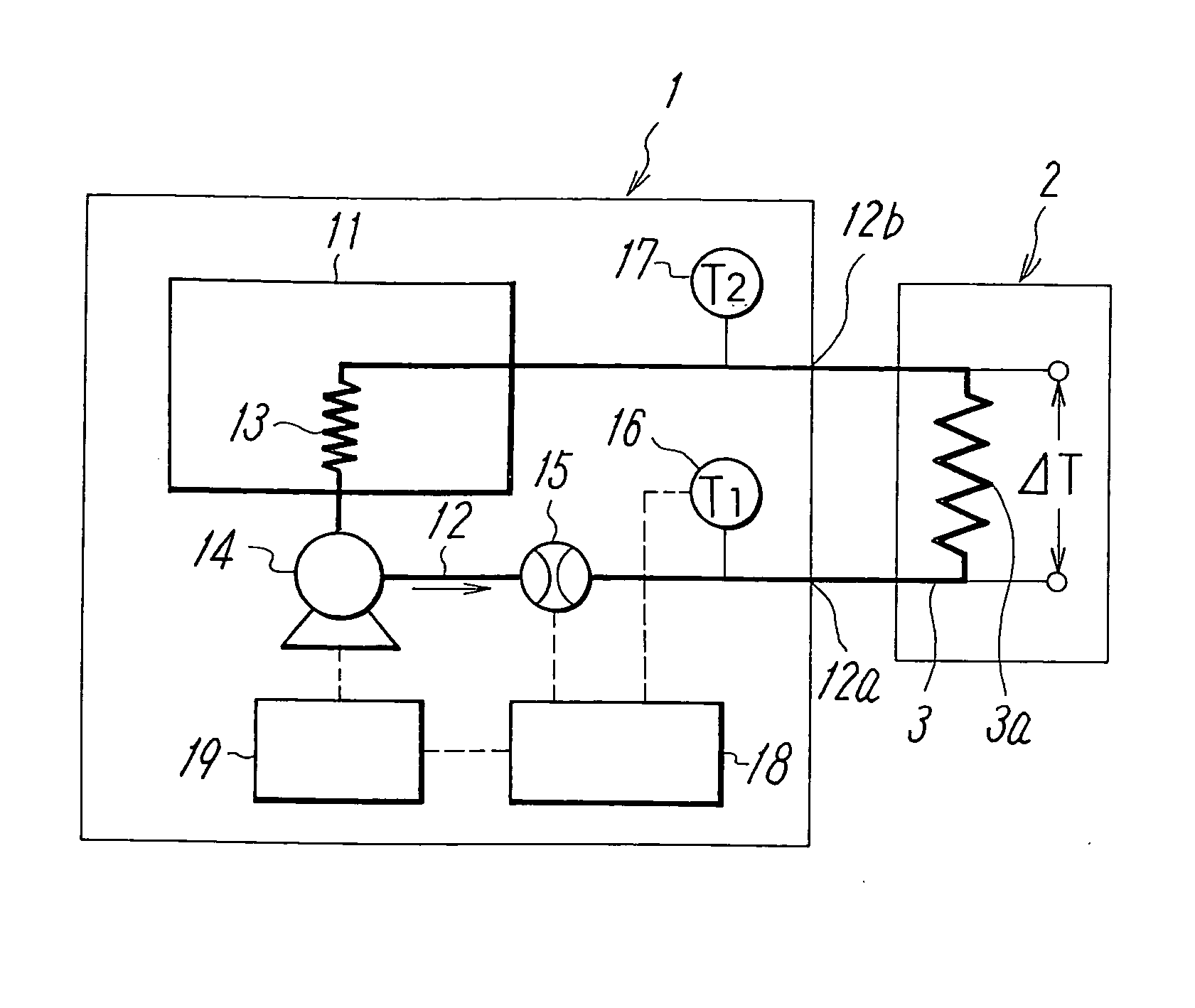
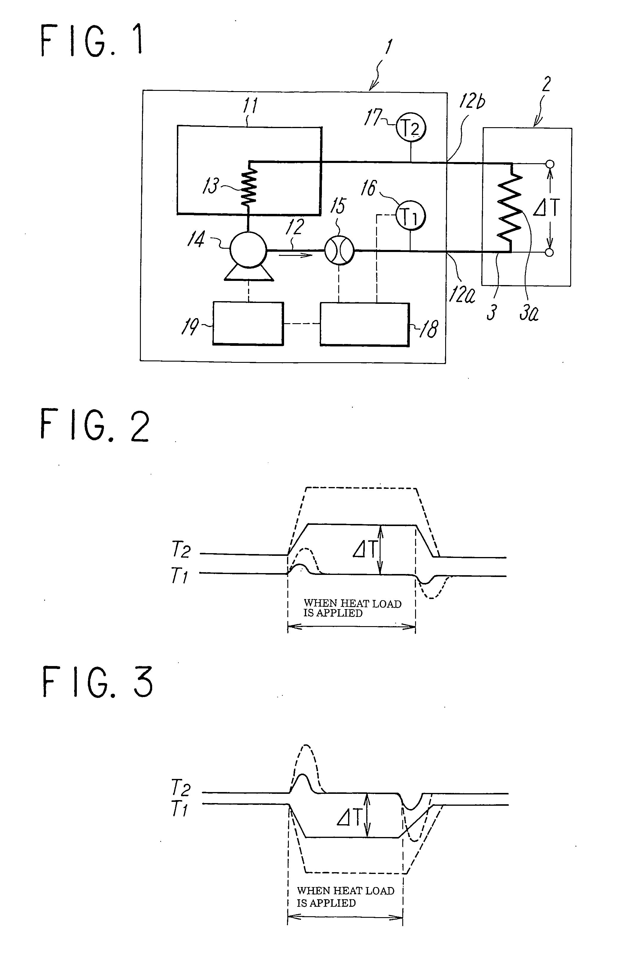
[0034]FIG. 1 shows the constant temperature liquid circulating device according to the present invention. The constant temperature liquid circulating device 1 includes a tank 11 for storing temperature controlling liquid, a conduit 12 having a discharge port 12a and a return port 12b for circulating the temperature controlling liquid in the tank 11 and the circulating liquid at a constant temperature which is heat-exchanged via a heat exchanger 13 to pass through a piping 3 of an external device 2, and a pump 14 provided in the conduit 12 for delivering the constant temperature circulating liquid to the piping 3 of the external device 2. The above-described conduit 12 is provided with a flow amount sensor 15 provided in series with the pump 14 and temperature sensors 16, 17 for detecting the discharged and return temperatures (T1, T2) of the circulating liquid in the vicinity of the discharge port 12a and the return port 12b of the conduit 12, and the flow amount or the pressure, an...

second embodiment

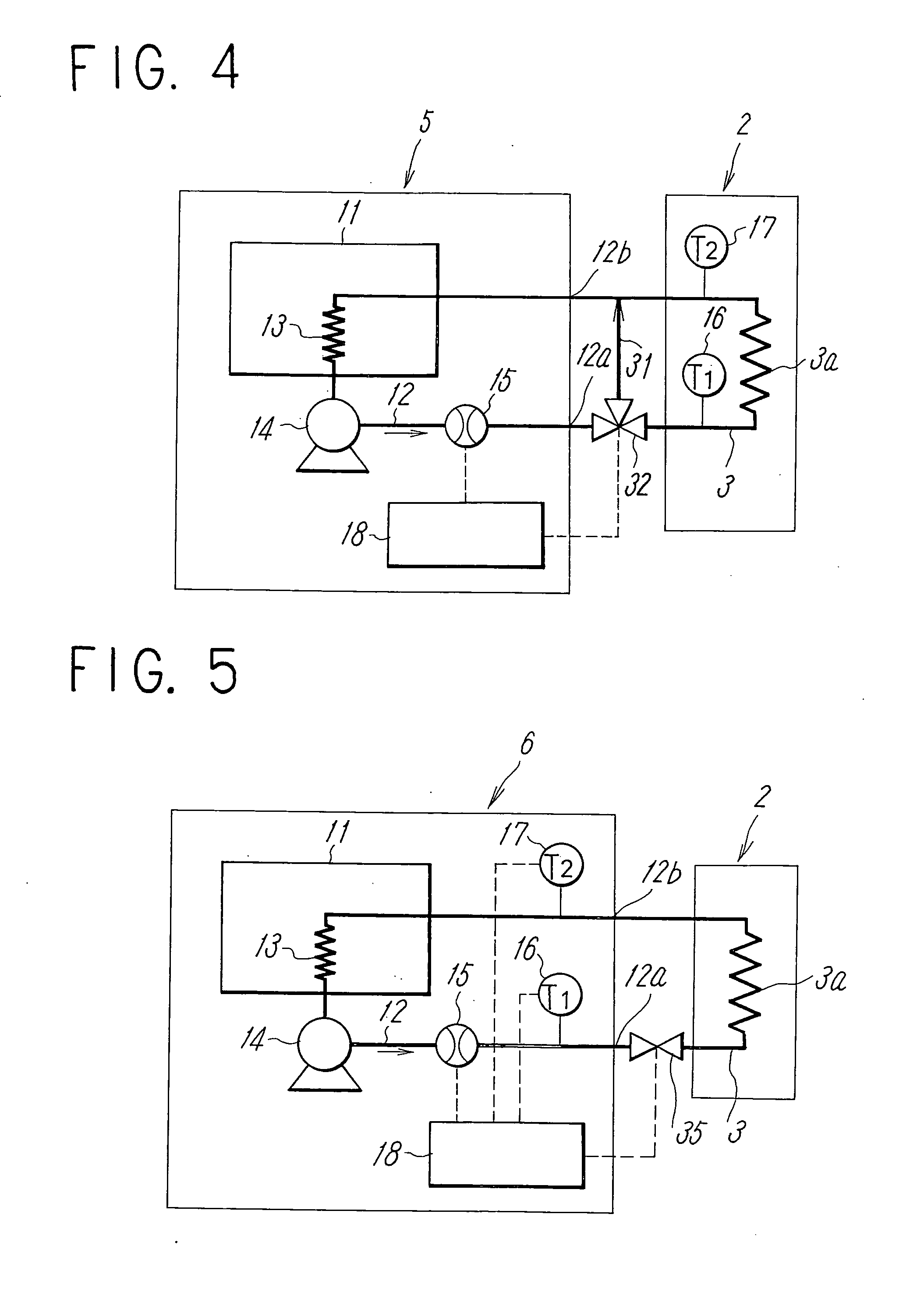
[0052] Referring now to FIG. 4, the constant temperature liquid circulating device according to the present invention will be described.

[0053] In the first embodiment, when providing the controller 18 with the controlling function for controlling the flow amount or the pressure of the circulating liquid to be delivered to the piping 3 of the external device 2, the number of rotations of the pump 14 is controlled by the inverter 19. In contrast to this configuration, a constant temperature liquid circulating device 5 in the second embodiment is provided with a bypass flow channel 31 for communicating the discharge port 12a and the return port 12b of the conduit 12 in the constant temperature liquid circulating device 5 with each other, and an electric valve 32 is provided in the bypass flow channel 31 for adjusting the flow amount of the liquid flowing therein from the discharge port 12a side to the return port 12b side to control the flow amount of the circulating liquid flowing in ...

third embodiment

[0059] Referring now to FIG. 5, the present invention will be described.

[0060] A constant temperature liquid circulating device 6 in the third embodiment includes an electric proportional valve 35 at the discharge port 12a of the conduit 12 of the constant temperature liquid circulating device 6 for controlling the flow amount of the circulating liquid flowing in the piping 3 of the external device 2 instead of the bypass flow channel 31 and the electric valve 32 in the second embodiment, and the electric proportional valve 35 is controlled by the controller 18 on the basis of the outputs from the temperature sensors 16, 17 to control the flow amount of the liquid flowing in the piping 3 of the external device 2, so that when the heat load in the external device 2 is increased, the electric proportional valve 24 is opened according to the heat load to increase the flow amount to the heat load portion 3a.

[0061] The temperature sensors 16, 17 in the third embodiment can be provided o...


PUM


Abstract

To reduce the width of variations in temperature of circulating liquid due to a variation in a heat load of an external device to a low level to stabilize the performance of the external device in a constant temperature liquid circulating device. In a constant temperature liquid circulating device that connects a piping of circulating liquid in an external device between a discharge port and a return port of a conduit for delivering the circulating liquid at a constant temperature by a pump, a flow amount sensor and temperature sensors for detecting discharge temperature (T1) of the circulating liquid from the conduit and the return temperature (T2) of the circulating liquid are provided in the conduit, so that the flow amount and the temperature of the circulating liquid is controlled by a controller according to the heat load of the external device obtained on the basis of the outputs from the temperature sensors. The control is such that when the difference between the discharge temperature and the return temperature is smaller than the preset value, the temperature of the circulating liquid is controlled corresponding to the heat load, and when the temperature difference is larger than the preset value, the temperature of the circulating liquid is controlled corresponding to the heat load by increasing the flow amount of the circulating liquid to the piping of the external device in addition to the temperature control described above.

Description

TECHNICAL FIELD [0001] The present invention relates to a constant temperature liquid circulating device in which a stable performance is obtained in an external device by reducing the width of variation in temperature of circulating liquid in association with variation in heat load of the external device to be controlled in temperature and a method of controlling the temperature in this device. BACKGROUND ART [0002] A constant temperature liquid circulating device including a conduit for delivering circulating liquid controlled to a constant temperature with a pump, wherein both ends of a piping that defines a flow channel for the circulating liquid in an exterior device to be controlled in temperature are connected to a discharge port and a return port of the conduit, respectively, is generally known as disclosed, for example, in Patent Document 1 and so on. [0003]FIG. 6 is an explanatory drawing showing a configuration of an example. A constant temperature liquid circulating devi...

Claims


Application Information

Patent Timeline
Patent Type & Authority Applications(United States)
IPC IPC(8): F24F11/04G05D23/00
CPCG05D23/192F28F27/00G05D7/0623G05D23/193G05D23/12
Inventor ICHINOSE, TAKEOSATO, KATSUTOSHI
Owner SMC CORP
Why Eureka
Try Eureka