Eureka AIR delivers breakthrough ideas for toughest innovation challenges, trusted by R&D personnel around the world.

Anode construction and method for deploying anode construction

Inactive Publication Date: 2017-08-24
BAC CORROSION CONTROL
View PDF1 Cites 0 Cited by
  • Summary
  • Abstract
  • Description
  • Claims
  • Application Information

AI Technical Summary

Benefits of technology

The invention described in this patent has various benefits and options for improvement. The terms "comprising" or "comprises" do not exclude other elements or steps. There may be multiple references, such as "a," but that doesn't mean there can only be one. Overall, the patent allows for flexibility and innovation in design and features.

Problems solved by technology

Relevant areas of deployment are numerous; however, constructions in operation in seawater are in particular prone to corrosion and will almost always be protected from such corrosion by means of cathodic protection using sacrificial anodes.
The oil exploitation constructions, pipelines or other equipment are however in many cases kept in operation well beyond the initial design life time, meaning that the cathodic protection obtained through the sacrificial anodes, will disappear when the anodes are consumed after a certain time.
Such previously known anode construction is relatively bulky and therefore difficult to transport from the production site to the actual operational site.
Although this previously known construction makes the transportation and deployment more convenient than a totally fixed construction, it is still a somewhat cumbersome and labour intensive process to fixate the joints of the anode carrying elements after alignment of these.
However, although this previously known construction also makes the transportation and deployment more convenient than a totally fixed construction, it is still a somewhat cumbersome and labour intensive process to bring the wing frame to its extended position and connect the plurality of wing frame supports to the wing frame in order to support the wing frame in its extended condition.

Method used


Image

  • Anode construction and method for deploying anode construction
  • Anode construction and method for deploying anode construction
  • Anode construction and method for deploying anode construction

Examples


Embodiment Construction

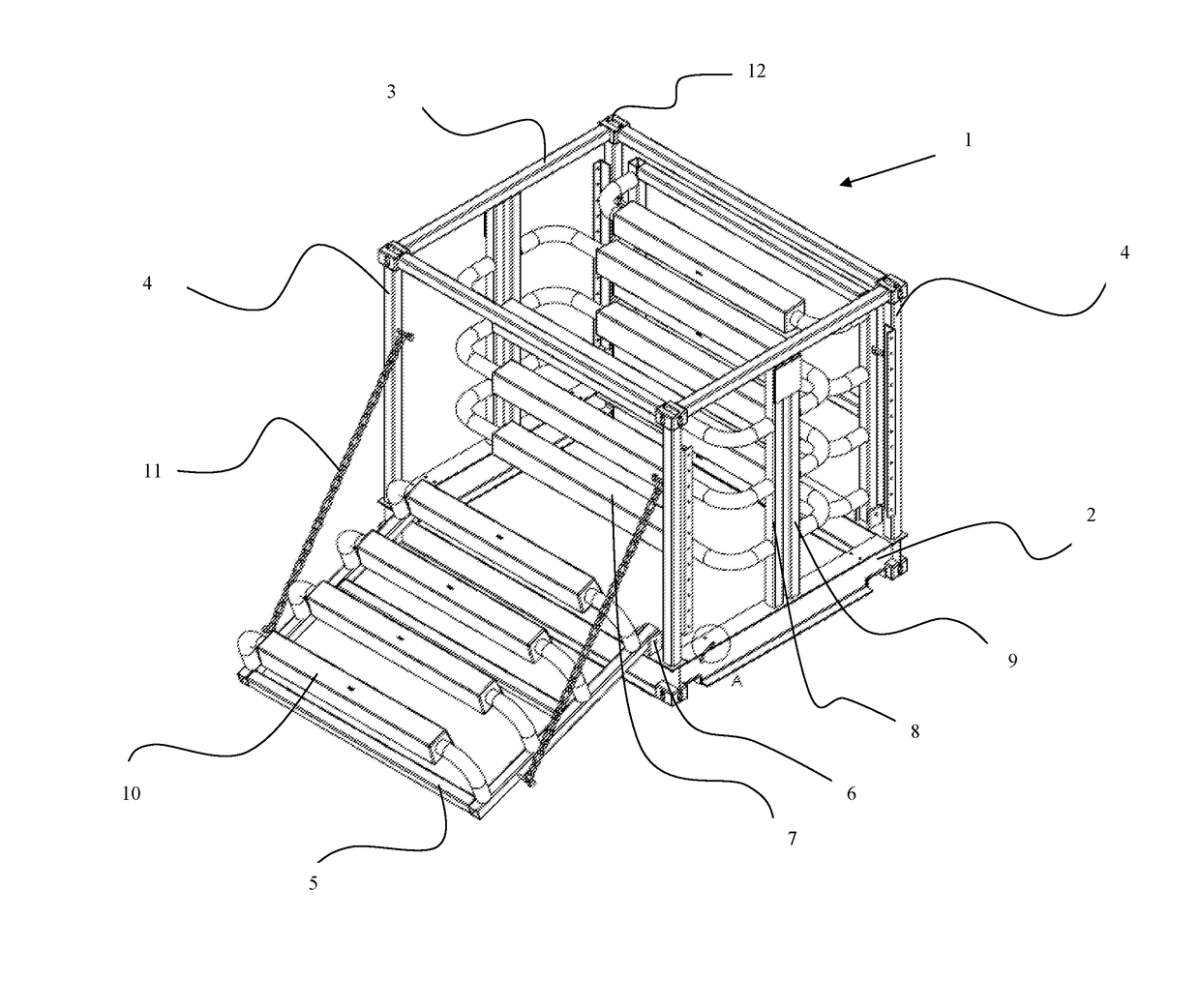
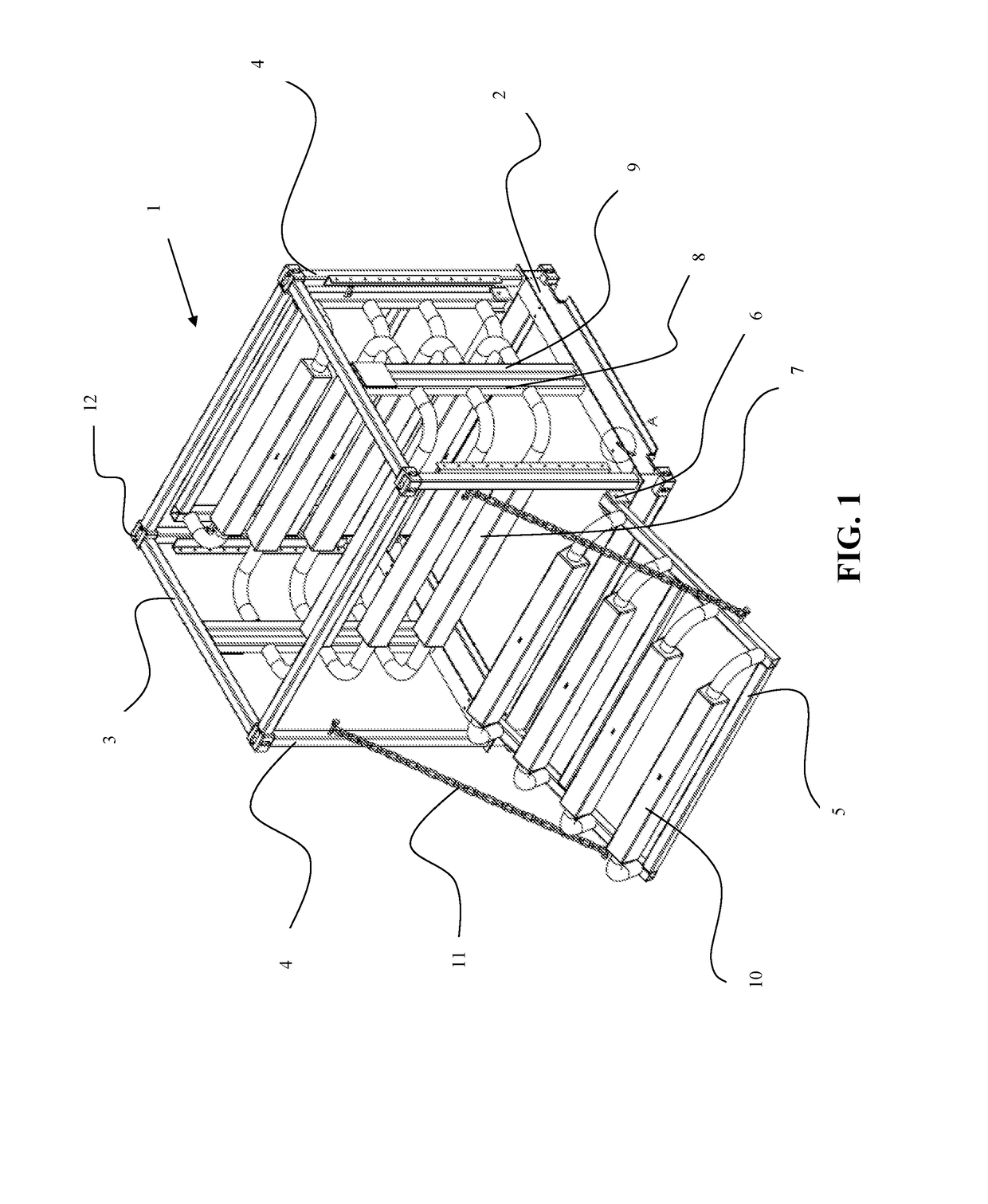
[0038]From FIG. 1 the anode construction 1 according to the invention appears in a perspective view. The construction comprises a frame with a rectangular bottom part 2 and a rectangular top part 3 and at four perpendicular corner posts 4 extending between the bottom part 2 and the top part 3. Between the corner posts 4 the frame defines two opposed side areas and two opposed end areas. At the end areas and between the top part and the bottom part, stationary anode carrier elements 8,9 are provided. The stationary anode carrier elements 8,9 carry six anode elements 7, three towards each side area. At each side area and connected to the bottom part 2 a pivotable side part 5 is provided, connected to the bottom part 2 through hinges 6 at each side of the pivotable side part 5. Each pivotable side part 5 carries four anode elements 10. In order to control the pivoting position chains 11 are provided between the pivotable side part 5 and the corner posts 4. This mainly serves the purpos...


PUM


Abstract

The invention relates to an anode construction comprising a frame with two or more anodes and being adapted to be used with an offshore installation for remote connection with the offshore installation through cable connections between anodes and offshore installation. The frame comprises a main part and at least one movable part mounted on the main part and adapted to be pivotable or slidable in relation to the main part, where one or more anodes are mounted in a fixed position on the main part and one or more anodes are mounted on the movable part. The main part has a bottom frame part and a top frame part and further at least two anode mounting columns between the bottom frame part and the top frame part, and where the fixed anodes are mounted on the anode mounting columns.

Description

FIELD OF THE INVENTION[0001]The present invention relates to the field of cathodic protection of metal constructions by use of sacrificial anodes.BACKGROUND OF THE INVENTION[0002]Cathodic protection using sacrificial anodes is a well-known area within a number of areas including ships, vessels and offshore constructions, e.g. oil exploitation rigs a.o.[0003]The electrochemical process taking place is generally along the following scheme for a ferrous material:Fe→Fe2++2e−O2+2H2O+4e−→4OH−2H2O+2e−→H2+2OH−[0004]In most environments, the hydroxide ions and ferrous ions combine to form ferroushydroxide, also known as rust:Fe2++2OH−→Fe(OH)2 [0005]It is desired to prevent or at least reduce the deterioration of the ferrous material, as this is the main structural material of the construction in question. Therefore a sacrificial metal ranking lower in the electrochemical scheme, and therefore being more prone to the electrochemical reaction, is placed in electrical connection with the main c...

Claims


Application Information

Patent Timeline
IPC IPC(8): C23F13/18C23F13/10
CPCC23F13/10C23F13/18C23F2213/31E02B17/0026
Inventor THOMSEN, CHRISTIAN PETER
Owner BAC CORROSION CONTROL
Why Eureka
Eureka Blog
Learn More