Identification of geometric deviations of a motion guide in a coordinate-measuring machine or in a machine tool

a technology of motion guide and coordinate measuring machine, which is applied in the direction of mechanical measuring arrangement, program control, instruments, etc., can solve the problems of hysteresis of measured geometric deviation, and achieve the effect of reducing the expenditure of tim

Active Publication Date: 2017-08-24
CARL ZEISS IND MESSTECHN GMBH
View PDF0 Cites 11 Cited by
  • Summary
  • Abstract
  • Description
  • Claims
  • Application Information

AI Technical Summary

Benefits of technology

[0010]It is an object of the present invention to specify a method for identifying geometric deviations of at least one motion guide in a coordinate-measuring machine or in a machine tool, which method permits exact identification of the geometric deviations with litt

Problems solved by technology

In particular drives that drive the movement of the movable part result in hysteresis of the measured geometric deviations, because the geometric deviation is dependent on the direction in which the movable part is moved along the motion guide.
If the t

Method used


Image

  • Identification of geometric deviations of a motion guide in a coordinate-measuring machine or in a machine tool
  • Identification of geometric deviations of a motion guide in a coordinate-measuring machine or in a machine tool
  • Identification of geometric deviations of a motion guide in a coordinate-measuring machine or in a machine tool

Examples


Embodiment Construction

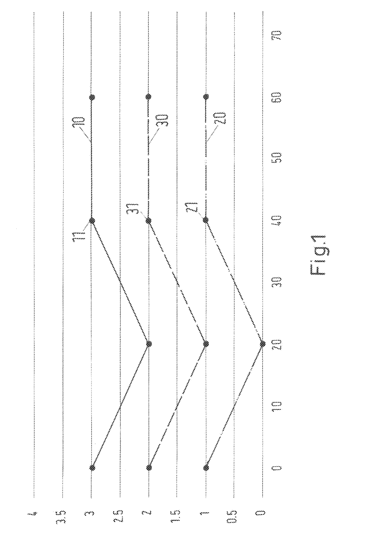
[0050]FIG. 1 shows an example of measured profiles (forwards direction at the bottom, backwards direction at the top), in which, at all measurement positions relating to the motion guide (in the example only four measurement positions), measurement values of the geometric deviation were recorded both during the movement in the forwards direction and also during the movement in the backwards direction. In contrast to the method of the present invention, no intermediate positions therefore exist at which measurement values were recorded for only one movement direction. The profile of the arithmetic average of the measurement values is situated between the measured profiles. The position along the guide is plotted (in the exemplary embodiment in millimeters) on the horizontal axis of the diagram. The geometric deviation relating to one degree of freedom is plotted (in the exemplary embodiment in micrometers) on the vertical axis. As in the following figures, this is a simplified exampl...


PUM


Abstract

The invention relates to a method for identifying geometric deviations of a real motion guide from an ideal motion guide in a coordinate-measuring machine having a sensor for measuring a workpiece, or in a machine tool having a tool for processing a workpiece, wherein the coordinate-measuring machine or the machine tool has a movable part which is guided along the motion guide and by the motion guide.

Description

CROSS-REFERENCE TO RELATED APPLICATION[0001]The present application is a continuation of International PCT application PCT / EP2015 / 073073, filed Oct. 6, 2015, which claims priority to German application No. DE 10 2014 220 313.9, filed Oct. 7, 2014. The entire contents of these priority applications are incorporated herein by reference.BACKGROUND OF THE INVENTION[0002]The invention relates to a method for identifying geometric deviations of a real motion guide from an ideal motion guide in a coordinate-measuring machine having a sensor for measuring a workpiece, or in a machine tool having a tool for processing a workpiece, wherein the coordinate-measuring machine or the machine tool has a part which is movable along the motion guide. The part can be in particular one where, during its movement, the sensor or the processing tool is moved. Alternatively, it can be a part which can be moved independently of the sensor or the processing tool. One example is a rotary table on which the wo...

Claims


Application Information

Patent Timeline
IPC IPC(8): G01B5/004G01B5/20G05B19/404G01B7/008G01B21/04B23Q17/22
CPCG01B5/004G01B21/042B23Q17/22G05B2219/39021G01B7/008G01B5/20G05B2219/50139G05B19/404G01B21/045G05B2219/37619G05B2219/49195
Inventor WERNER, ELMARFUCHS, ANDREASBULLING, DOMINIC
Owner CARL ZEISS IND MESSTECHN GMBH
Why Eureka
Try Eureka