Directed-energy weapon and method for displaying the position of an impact point of the directed-energy weapon

a technology of directed energy and impact points, which is applied in the direction of directed energy weapons, weapons, aiming means, etc., can solve the problems of difficult target point determination, inability to avoid weapon movement, and inability to achieve the method in the operation region of the weapon

Pending Publication Date: 2022-09-29
RHEINMETALL WAFFE MUNITION GMBH
View PDF0 Cites 0 Cited by
  • Summary
  • Abstract
  • Description
  • Claims
  • Application Information

AI Technical Summary

Problems solved by technology

Another disadvantage is that this target point determination is very difficult when the weapon is in motion.
A movement of the weapon can hardly be avoided in the case of ship weapons, for example.
It is also disadvantageous that the method may not be feasible in the operation region of the weapon if it is not a restricted region.
Then, for example, after a weapon repair, an exact target point determination of the directed-energy weapon is not possible.

Method used


Image

  • Directed-energy weapon and method for displaying the position of an impact point of the directed-energy weapon
  • Directed-energy weapon and method for displaying the position of an impact point of the directed-energy weapon
  • Directed-energy weapon and method for displaying the position of an impact point of the directed-energy weapon

Examples


Embodiment Construction

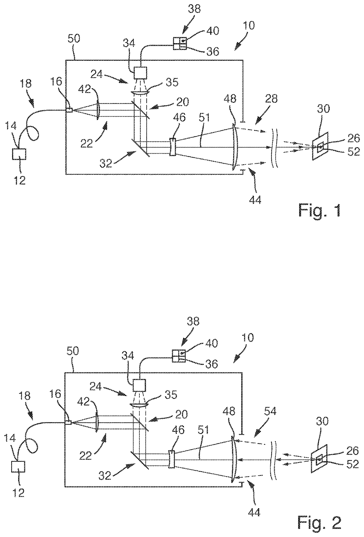
[0043]In detail, FIG. 1 shows a simplified illustration of a directed-energy weapon 10. The directed-energy weapon 10 has a primary radiation source 12 and at least one radiation-guiding solid body 18 having a first end 14 and a second end 16 as well as a first wavelength splitter or beam splitter 20. The primary radiation source 12 preferably has one or more lasers. The radiation-guiding solid body 18 is, for example, a glass fiber or a glass fiber bundle.

[0044]The directed-energy weapon 10 has an effective beam optical system 22 and an imaging optical system 24 and is configured to display the position of an impact point 26 of the directed-energy weapon 10. The effective beam optical system 22 is configured to focus and align the primary radiation of the directed-energy weapon 10 to be emitted as an effective beam 28 or an auxiliary beam into a target plane 30. The alignment is carried out, for example, by a movable deflecting mirror 32.

[0045]The imaging optical system 24 is confi...


PUM


Abstract

A method and apparatus for displaying a position of an impact point of a directed-energy weapon which has an effective beam optical system and an imaging optical system. An emission of primary radiation of the directed-energy weapon is triggered as an effective beam, and radiation exiting from an irradiated object is received by the imaging optical system and directed onto a camera of a screen. A beam bundle cross section of an effective beam is covered with a reflective optical auxiliary element, the effective beam or the auxiliary beam is triggered with the beam bundle cross section covered, and primary radiation of the effective beam or of the auxiliary beam which is reflected by the reflective optical auxiliary element is received by the imaging optical system and directed onto a spot of the camera as the impact point.

Description

[0001]This nonprovisional application is a continuation of International Application No. PCT / EP2019 / 079143, which was filed on Oct. 25, 2019 and which claims priority to German Patent Application No. 10 2018 126 833.5, which was filed in Germany on Oct. 26, 2018 and which are both herein incorporated by reference.BACKGROUND OF THE INVENTIONField of the Invention[0002]The present invention relates to a method for displaying an actual impact point of a directed-energy weapon and to a directed-energy weapon.Description of the Background Art[0003]A method and a directed-energy weapon are known in the conventional art per se. The conventional method relates to a directed-energy weapon which has an effective beam optical system and an imaging optical system. The effective beam optical system is used to focus and align primary radiation that is emitted by the directed-energy weapon in the form of an effective beam or an auxiliary beam. Radiation exiting from an object irradiated with the e...

Claims


Application Information

Patent Timeline
Patent Type & Authority Applications(United States)
IPC IPC(8): F41H13/00
CPCF41H13/0062F41G3/323F41G3/165F41H13/005
Inventor LUDEWIGT, KLAUS
Owner RHEINMETALL WAFFE MUNITION GMBH
Why Eureka
Try Eureka