
Real-time simulation of the operation of a specific electrice motor

a specific electric motor and real-time simulation technology, applied in the field of computerimplemented methods for real-time simulation of the operation of specific electric motors, can solve the problems of generating motors with little time expenditure, existing motor models that had to be laboriously adapted and implemented, and not covering all boundary conditions in the individual motor model library

Pending Publication Date: 2021-10-28
DSPACE DIGITAL SIGNAL PROCESSING & CONTROL ENG
View PDF0 Cites 0 Cited by
  • Summary
  • Abstract
  • Description
  • Claims
  • Application Information

AI Technical Summary

Benefits of technology

The present invention provides a method for quickly generating motor models that can cover a wide variety of topologies and boundary conditions, without requiring significant time expenditure. The method uses an automated process with a dynamic library to implement different types of motors and their variants quickly on an FPGA. A library is used that contains the necessary arithmetic operations for calculating the operation of the specific motor. The method can be used for multiple motors simultaneously, and a switch between motor variants or fault simulation variants can be implemented in a time-optimized manner. Overall, this approach offers a more efficient and flexible means for generating and simulating motor models.

Problems solved by technology

However, the individual motor models in the library do not cover all boundary conditions and are therefore subject to certain limitations.
Up to now, existing motor models therefore had to be laboriously adapted and implemented on programmable logic devices in order to cover the required boundary conditions.
In individual cases, it was therefore sometimes very difficult, for example, to represent motors with more than three phases or represent electrical fault simulation.

Method used


Image

  • Real-time simulation of the operation of a specific electrice motor
  • Real-time simulation of the operation of a specific electrice motor
  • Real-time simulation of the operation of a specific electrice motor

Examples


Embodiment Construction

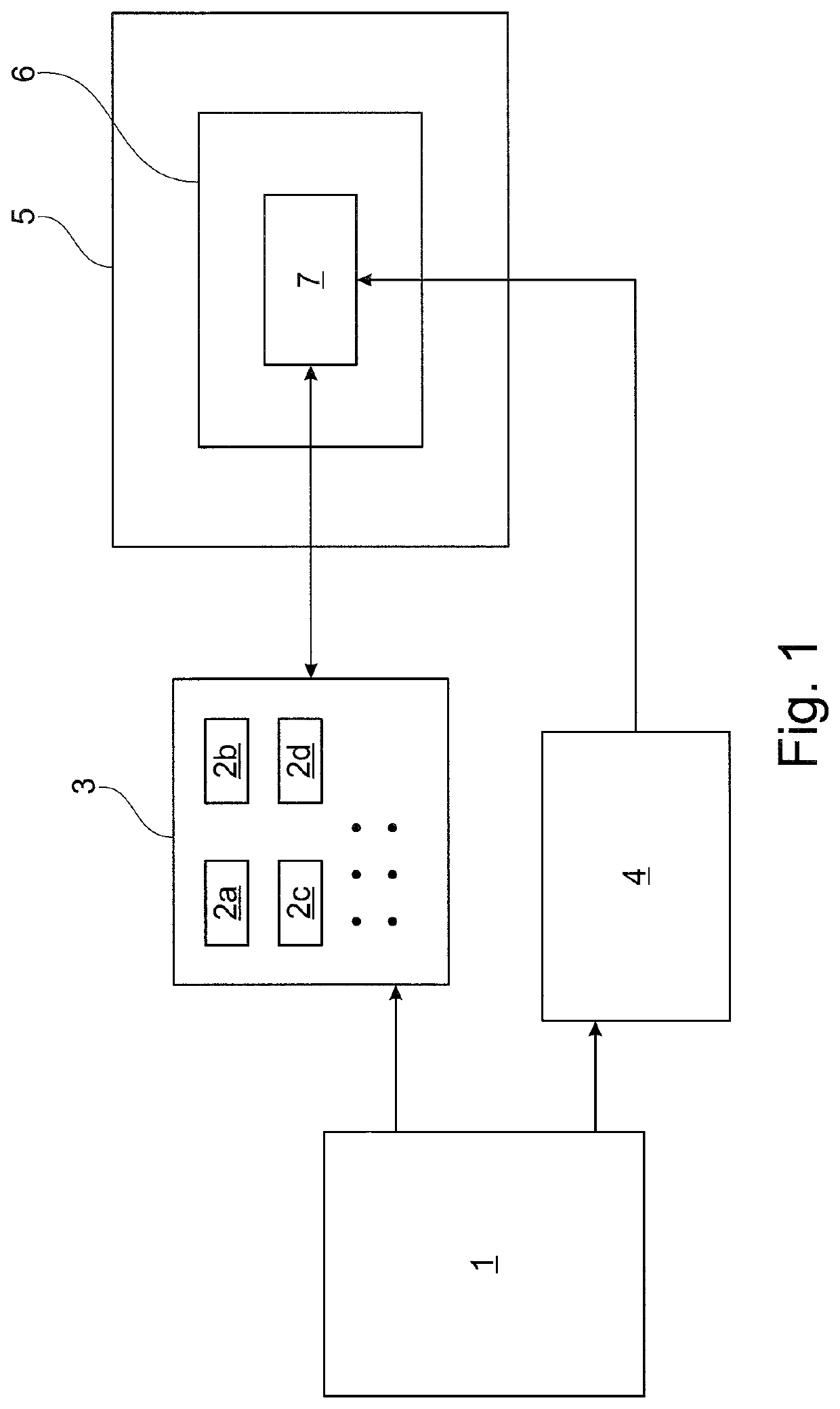
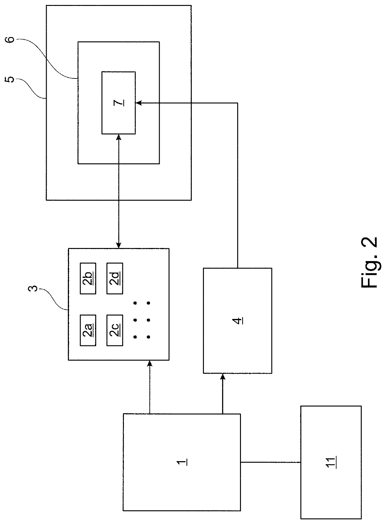
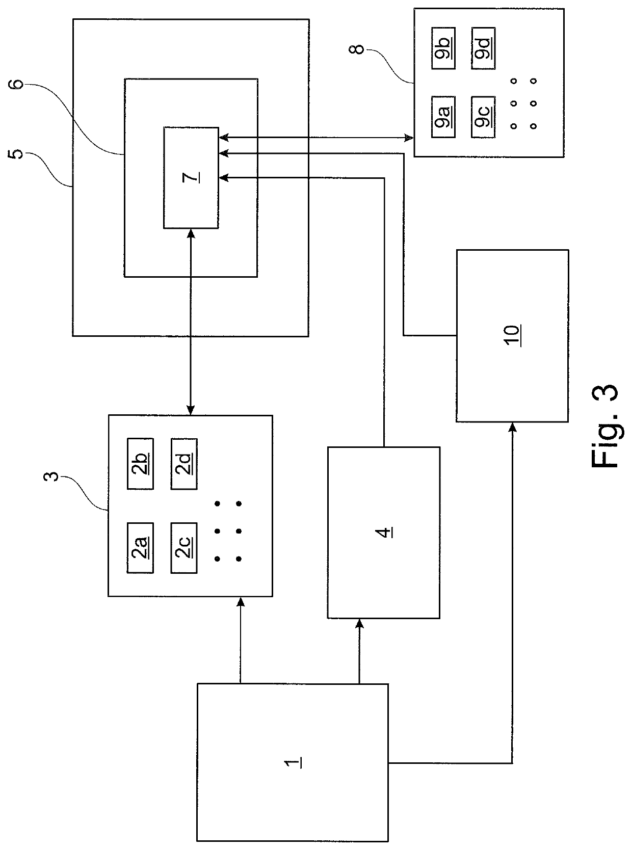
[0033]The model on which the simulation is based is described in a generic system of equations according to the preferred embodiment of the invention described herein. The arithmetic operations required for this are contained in a textual description. When a simulation project is created, the system of equations is parameterized for the specific case of relevant boundary conditions, namely by means of those that are given by the specific electric motor to be simulated. According to the preferred embodiment of the invention described herein, a dynamic library of blocks containing the necessary arithmetic operations (basic arithmetic operations, matrix multiplication, coordinate transformation) is then automatically generated from the parameterized textual description. The actual motor model is available on a programmable logic device as a fixed structure of references to library elements, i.e., the arithmetic operations stored in the library. With the generation of the library these ...


PUM


Abstract

A computer-implemented method for real-time simulation of the operation of a specific electric motor by a simulator arithmetic unit comprising a programmable logic device on which a generic motor model is implemented. The method includes: providing a generic system of equations corresponding to the generic motor model; receiving specific information corresponding to the specific motor to be simulated for the generic system of equations and inputting this information into the generic system of equations; generating a specific library containing at least some of the arithmetic operations required for the matrix operations for calculating the operation of the specific motor; implementing references in the generic motor model to the arithmetic operations of the specific library required for real-time simulation of the operation of the specific electric motor; and simulating the operation of the specific electric motor by running the generic motor model on the simulator arithmetic unit.

Description

[0001]This nonprovisional application claims priority under 35 U.S.C. § 119(a) to German Patent Application No. 10 2020 111 044.8, which was filed in Germany on Apr. 23, 2020 and which is herein incorporated by reference.BACKGROUND OF THE INVENTIONField of the Invention[0002]The present invention relates to a computer-implemented method for real-time simulation of the operation of a specific electric motor by means of a simulator arithmetic unit comprising a programmable logic device (FPGAs—field-programmable gate array).Description of the Background Art[0003]Known from the prior art is, for example, the library “XSG Electric Components Library” (XSG EC Lib) originating from the applicant, which provides system models for FPGA-based simulation of electrical components. Electrical motor control applications that require high precision and sampling rates are typically simulated on a programmable logic device. To maintain identical processes during controller development and testing, t...

Claims


Application Information

Patent Timeline
Patent Type & Authority Applications(United States)
IPC IPC(8): G06F30/20H03K19/173
CPCG06F30/20G06F2111/10H03K19/173G06F2111/16
Inventor BOBE, BJOERN
Owner DSPACE DIGITAL SIGNAL PROCESSING & CONTROL ENG
Learn More