Markings of highly viscous material on a surface

a technology of viscosity and surface, applied in the direction of roads, roads, highways, etc., can solve the problems of reducing quality, reducing the quantity of color mass, and reducing the quality of the surface, so as to achieve low acquisition cost, reduce the risk of loose marking material when a snowplow drives over it, and improve the quality.

Inactive Publication Date: 2016-07-05
HOFMANN MASCHFAB & VERTRIEB
View PDF11 Cites 0 Cited by
  • Summary
  • Abstract
  • Description
  • Claims
  • Application Information

AI Technical Summary

Benefits of technology

[0014]Advantageously, the plurality of marking material flows is less susceptible to interferences caused by clumping or foreign objects in the marking material as a single thin band-shaped or curtain-shaped marking material flow, whereby the appearance of interferences and interruptions is rarer. Due to the plurality of marking material flows, which are discharged next to one another, the impact of the material viscosity on the line width of the marking line is also considerably lower than in the case of a band-shaped or curtain-shaped material flow. The method according to the invention can thereby advantageously be carried out in a closed system without the known, above-mentioned disadvantages of open systems comprising draw or feed boxes, which avoids a hardening of marking material prior to being discharged onto the surface, which is to be marked. The fact that the marking material is discharged continuously or so as to pulsate or intermittently from a plurality of discharge nozzles in a pressurized manner will contribute to a reliable process flow. In addition, a high speed can be reached in response to the production of the markings in this manner. Due to the fact that the individual marking material flows are turned on or off in accordance with the marking, which is to be created, the width of a marking, which is to be created, can in particular be changed in a simple manner.
[0030]An advantageous embodiment of the device according to the invention finally provides for the rotational body / bodies including a rotational body support and, if applicable, one or a plurality of rotational body drives to be embodied as an additional unit, which can be mounted to the remaining device and which can be separated from the remaining device. In this embodiment, the device can be modified quickly and easily between two different versions, wherein, in the first version without the rotational body / bodies, markings can be created, which consist of a plurality of marking material points, which are relatively identical, while in the second version comprising the rotational body or the rotational bodies, markings comprising a stochastic material distribution can be created. The change between the two versions of the device can thereby be realized with little modification effort. In addition, the relatively low acquisition costs and the small expenditure of time for the modification are advantageous, when, in the case of a device, which is already at hand, only the additional unit must be acquired for creating markings of uniform marking materials points, so as to then also be able to create markings comprising a stochastic material distribution. For example, the version of the device, which was mentioned first above, can be embodied according to DE 10 2009 045 576 A1 by applicant, to which reference is made herein.

Problems solved by technology

In the case of markings comprising a stochastic material distribution, the risk that the marking material comes loose when a snowplow drives over it, is also small.
It is considered to be a disadvantage in this state of the art that the volume flow of the color mass from the open storage container through the outlet gap strongly depends on the level of the color mass in the open storage container and fluctuates with this level.
As a result, the quantity of the color mass, which is discharged for each unit of stretch of road, which the vehicle covers, is not constant.
This leads to irregular road markings, which means a reduced quality.
In addition, the marking speed, which can be reached, is limited, because the color mass is dispensed from the storage container solely by means of the force of gravity.
This state of the art furthermore encompasses the disadvantage that the marking process needs to be interrupted at relatively short intervals as a function of the hardening time of the marking material, so as to clean the device parts touched by the marking material, in particular the storage container and the guide plate.
This means lower daily outputs and a high flushing fluid consumption, which leads to high costs and to environmental pollution.
In the case of the slot-shaped material outlet, the material flow can furthermore be hindered easily, e.g. because clumps get caught in the slot, which requires a relatively frequent cleaning of the outlet.
In addition to the above-mentioned disadvantages, this state of the art encompasses the further disadvantage that the marking material, which is applied herein in the form of a flat belt or curtain, has the characteristic that, due to acceleration caused by the force of gravity and wall friction at the outlet walls, the material flow is constricted after leaving the slot-shaped outlet prior to striking the rotational body.
As a result, the line width of the marking line is thus always smaller than the slot width of the outlet to an extent, which cannot be determined accurately ahead of time.
It is considered to be disadvantageous in the case of this state of the art that the marking material, which adheres to the separating walls and which hardens at that location, can relatively easily lead to impairments of the movement of the rotating paddles.
A cleaning of the relatively narrow outlets is difficult and time-consuming.
Structured markings comprising a stochastic material distribution cannot be created by means of this device.

Method used


Image

  • Markings of highly viscous material on a surface
  • Markings of highly viscous material on a surface
  • Markings of highly viscous material on a surface

Examples


Embodiment Construction

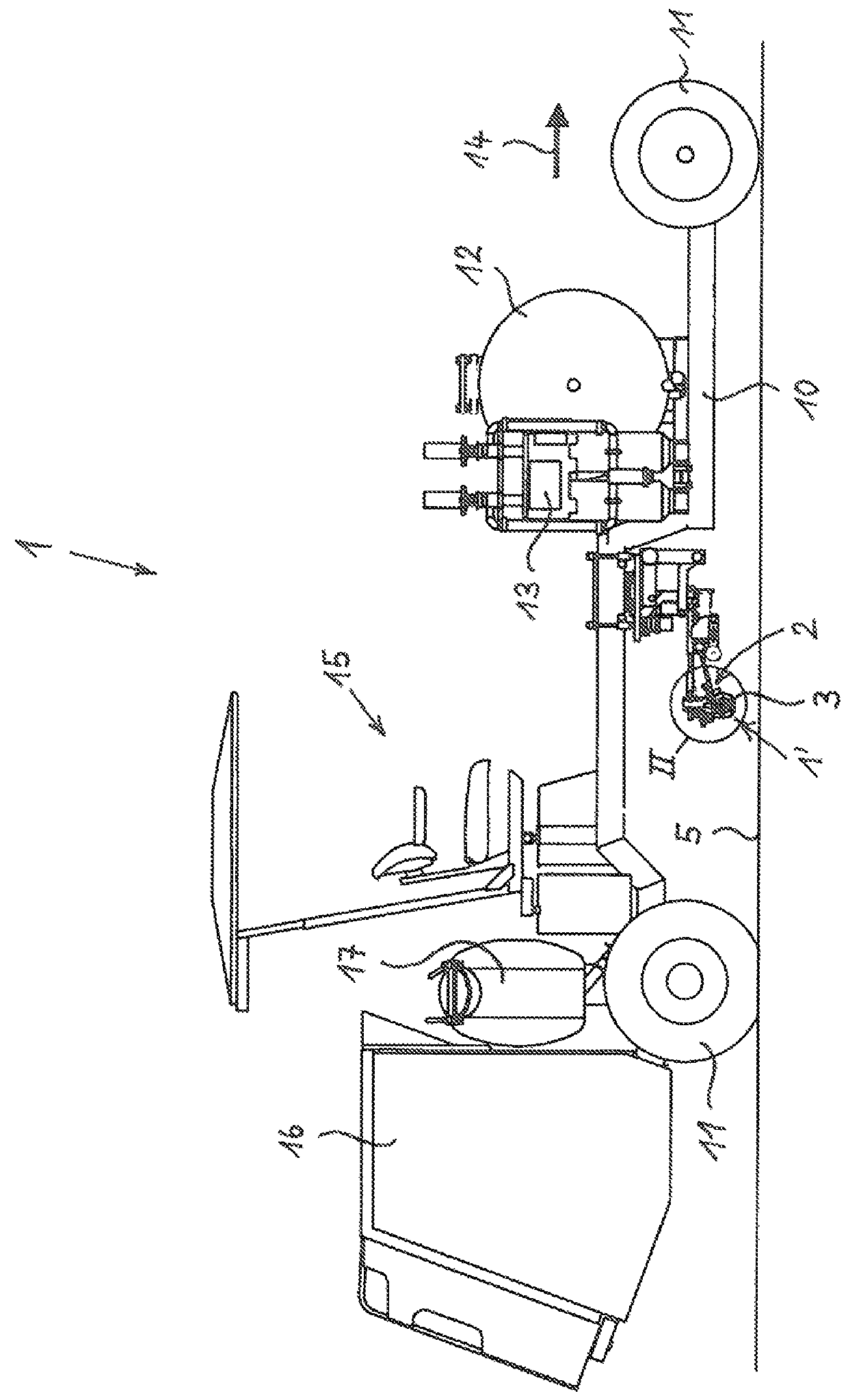
[0040]FIG. 1 of the drawing shows a device 1 for creating markings on a surface 5, which is to be marked, in a schematic side view. The device 1 is embodied herein as a self-propelled vehicle comprising a frame 10 and four wheels 11, as well as with a drive unit 16, such as an internal combustion engine and transmission arranged on the rear, and comprising a driver's cab 15 for an operator. In the alternative, the device 1 can also be embodied as a pulled vehicle without its own propulsion.

[0041]In the front part of the device 1, on the right-hand side in FIG. 1, at least one storage container 12 for marking material is arranged on the frame 10. A conveying device 13, here a metering pump, which, on the input side, is connected to the interior of the storage container 12 via lines, which are not visible herein, and which, on the output side, is connected to a material outlet 2 for discharging marking material to the surface 5, which is to be marked, such as a road surface, is connec...


PUM


Abstract

A method and device for creating markings of highly viscous marking material on a surface, in particular a road surface. The marking material is discharged from a material supply and, before striking the surface is fed to a rotational body, which moves relative to the surface in a longitudinal direction of the marking, and is applied to the surface divided into unequal material portions by the rotational body. The rotational body axis of rotation runs at right angles to the marking longitudinal direction. The marking material is fed to the rotational body in a plurality of marking material flows, which, viewed in a longitudinal direction of the rotational body, are discharged next to one another from a plurality of discharge nozzles continuously, pulsatingly or intermittently in a pressurized manner. The individual marking material flows are turned on or off in accordance with the marking to be created.

Description

CROSS-REFERENCES TO RELATED APPLICATIONS[0001]This application claims the benefit of the German patent application No. 10 2012 221 834.3 filed on Nov. 29, 2012, the entire disclosures of which are incorporated herein by way of reference.BACKGROUND OF THE INVENTION[0002]The invention relates to a method for creating markings, in particular marking lines of highly viscous marking material, in particular a two-component cold plastic, on a surface, which is to be marked, in particular a road surface, wherein the marking material is discharged from a material supply and, before striking the surface, which is to be marked, is fed to a rotational body, which moves relative to the surface in longitudinal direction of the marking, which is to be created, and is applied to the surface so as to be divided into unequal material portions by means of said rotational body, wherein the axis of rotation of the rotational body runs at right angles to the longitudinal direction of the marking and wher...

Claims


Application Information

Patent Timeline
Patent Type & Authority Patents(United States)
IPC IPC(8): E01C23/24E01C23/22
CPCE01C23/222E01C23/24
Inventor HOFMANN, JAN PHILIPP
Owner HOFMANN MASCHFAB & VERTRIEB
Why Eureka
Try Eureka