Geometry measurement system, geometry measurement apparatus, and geometry measurement method

a technology of geometry measurement and measurement method, applied in the field of geometry measurement system, geometry measurement apparatus, and geometry measurement method, can solve the problems of high degree of cleanliness, method cannot be used, and the geometry of the object to be measured is altered

Active Publication Date: 2017-08-24
MITUTOYO CORP
View PDF2 Cites 12 Cited by
  • Summary
  • Abstract
  • Description
  • Claims
  • Application Information

AI Technical Summary

Benefits of technology

[0005]Accordingly, the present invention has been made in view of these problems, and an object thereof is to provide a geometry measurement system, a geometry measurement app

Problems solved by technology

However, the method of applying a coating material to the object to be measured is associated with a problem wherein the geometry of the object to be measured is altered due to the application of the coating material, a problem wherein the number of man-hours for applying the coating material to the object to be measured and for rinsing the coating material is increased, and a

Method used


Image

  • Geometry measurement system, geometry measurement apparatus, and geometry measurement method
  • Geometry measurement system, geometry measurement apparatus, and geometry measurement method
  • Geometry measurement system, geometry measurement apparatus, and geometry measurement method

Examples


first embodiment

[Outline of Geometry Measurement System S]

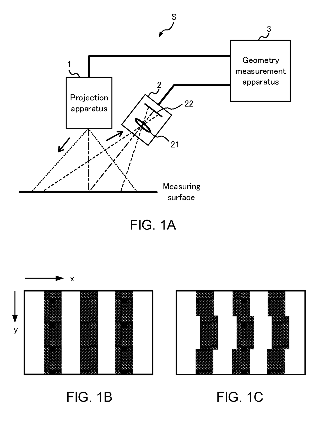
[0030]FIG. 1 contains diagrams for illustrating the outline of the geometry measurement system S according to the first embodiment. FIG. 1A shows the configuration of the geometry measurement system S. The geometry measurement system S includes a projection apparatus 1, an imaging apparatus 2, and a geometry measurement apparatus 3.

[0031]The projection apparatus 1 includes a light source, such as a light emitting diode, laser, or the like, and projects a plurality of projection patterns, each projection pattern being different from one another, onto a measuring surface of the object to be measured. The imaging apparatus 2 includes a lens 21 and an imaging element 22, and generates a plurality of captured images by imaging the object to be measured, in a sequential manner, while the projection apparatus 1 projects each of the plurality of the projection patterns. The geometry measurement apparatus 3 measures the geometry of the object to be m...

embodiment

[0073]FIG. 9 contains diagrams showing the relationship between a luminance value and a quantization value of a pixel (x, y) in a captured image. The horizontal axis indicates the projection pattern types and the vertical axis indicates the luminance value in the captured image. Solid-line arrows indicate the luminance values attributed to direct light and broken-line arrows indicate the luminance values attributed to the multiple reflection light. For the projection patterns where the solid-line arrows exist, light is projected onto the pixel (x, y). For the projection patterns where the broken-line arrows exist, light is not projected onto the pixel (x, y). Accordingly, light is projected onto the pixel (x, y) only in projection patterns 1, 2 and 4, and if there is no influence of the multiple reflection light, the code value for this pixel (x, y) is C=(c1, c2, c3, c4)=(1, 1, 0, 1).

[0074]In FIG. 9A, the quantization values after the multiple reflection light is added are also (1, ...

example 1

Variation Example 1

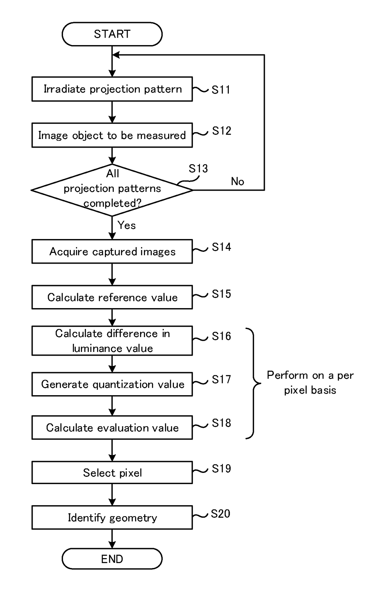
[0076]In the description above, the quantization part 322 sets, as the reference value, an intermediate luminance value between the luminance value of an all-black captured image (first captured image) imaged by the imaging apparatus 2 under the circumstances where light is not projected onto the object to be measured and the luminance value of an all-white captured image (second captured image) imaged by the imaging apparatus 2 under the circumstances where light is projected onto the entire object to be measured. However, the reference value may be any other value. The luminance value of the captured image imaged by the imaging apparatus 2 under the circumstances where light is projected onto the entire object to be measured tends to be larger than the luminance value of the captured image imaged under the circumstances where the projection patterns 1 to 4 are projected onto the object to be measured. Accordingly, when quantizing the luminance value of the captu...


PUM


Abstract

The geometry measurement apparatus includes: an image acquisition part that acquires a plurality of captured images generated by imaging an object to be measured, onto which a plurality of respectively different projection patterns are sequentially projected; a quantization part that generates a quantization value of a luminance value for each pixel in the plurality of captured images by comparing the luminance value with a predetermined reference value; a selection part that selects, based on the relationship between the reference value and the luminance value for a plurality of pixels having the same coordinates in the plurality of captured images, a quantization value to be used for identifying the geometry of the object to be measured, from among a plurality of quantization values corresponding to the plurality of captured images; and a geometry identification part that identifies the geometry of the object to be measured based on the quantization value selected by the selection part.

Description

CROSS-REFERENCE TO RELATED APPLICATIONS[0001]The present application claims priority to Japanese Patent Application number 2016-028851, filed on Feb. 18, 2016. The content of this application is incorporated herein by reference in its entirety.BACKGROUND OF THE INVENTION[0002]Traditionally, methods are known in which a predetermined projection pattern is projected onto an object to be measured, and the geometry thereof is measured, without making contact with the object to be measured, by analyzing a captured image obtained by imaging the object to be measured, onto which a light beam is projected. JP 2009-094295 A discloses a measurement apparatus for measuring a height of an electronic component based on a captured image obtained by imaging an optical cutting line when line light is projected onto the electronic component.[0003]When a projection pattern is projected onto the object to be measured, multiple reflections may occur, which is light reflection among a plurality of surfa...

Claims


Application Information

Patent Timeline
IPC IPC(8): G01B11/00G06T7/73G06K9/62G06K9/52G06K9/46G06V10/145G06V10/60
CPCG01B11/002G06K9/52G06T7/73G06K9/6215G06K9/4604G06K9/4661G01B11/2545G06T7/521G06V10/145G06V10/60G06F18/22
Inventor MIYATA, KAORU
Owner MITUTOYO CORP
Why Eureka
Try Eureka