Light guiding structure for guiding light transmitted from a plurality of light emitting components and light emitting device therewith

Active Publication Date: 2017-08-24
WISTRON CORP
View PDF3 Cites 5 Cited by
  • Summary
  • Abstract
  • Description
  • Claims
  • Application Information

AI Technical Summary

Benefits of technology

The present disclosure is a light guiding structure that prevents interference between different light emitting components on a circuit board. This allows for a dense distribution of the light emitting components and saves mechanical space during assembly. The light emitting device can display accurate colored light at the correct position, providing users with valuable operational information. The light emitting components are placed in light guiding columns, which concentrate the light and prevent unnecessary loss. The light is then diverged by concave surfaces, allowing for easy observation at any angle. Overall, this patent improves the efficiency and user experience of light emitting devices.

Problems solved by technology

At this moment, the positions on the panel module cannot display the correct light corresponding to the light emitting components, so that the users cannot judge the current operational condition of the electronic device according to the positions of the light displayed on the panel module correctly.
Furthermore, when the plurality of light emitting components emits light with different colors to the same light guiding structure at the same time, the color of the light displayed on the panel module is mixed, so that the users cannot judge the current operational condition of the electronic device according to the color of the light displayed on the panel module correctly.
However, it not only requires a larger mechanical space and but also results in assembling difficulty.

Method used


Image

  • Light guiding structure for guiding light transmitted from a plurality of light emitting components and light emitting device therewith
  • Light guiding structure for guiding light transmitted from a plurality of light emitting components and light emitting device therewith
  • Light guiding structure for guiding light transmitted from a plurality of light emitting components and light emitting device therewith

Examples


Embodiment Construction

[0020]In the following detailed description of the preferred embodiments, reference is made to the accompanying drawings which form a part hereof, and in which is shown by way of illustration specific embodiments in which the disclosure may be practiced. In this regard, directional terminology, such as “top,”“bottom,”“front,”“back,” etc., is used with reference to the orientation of the Figure(s) being described. The components of the present disclosure can be positioned in a number of different orientations. As such, the directional terminology is used for purposes of illustration and is in no way limiting. Accordingly, the drawings and descriptions will be regarded as illustrative in nature and not as restrictive.

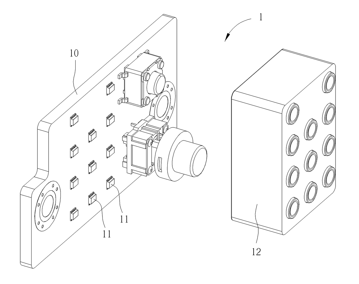
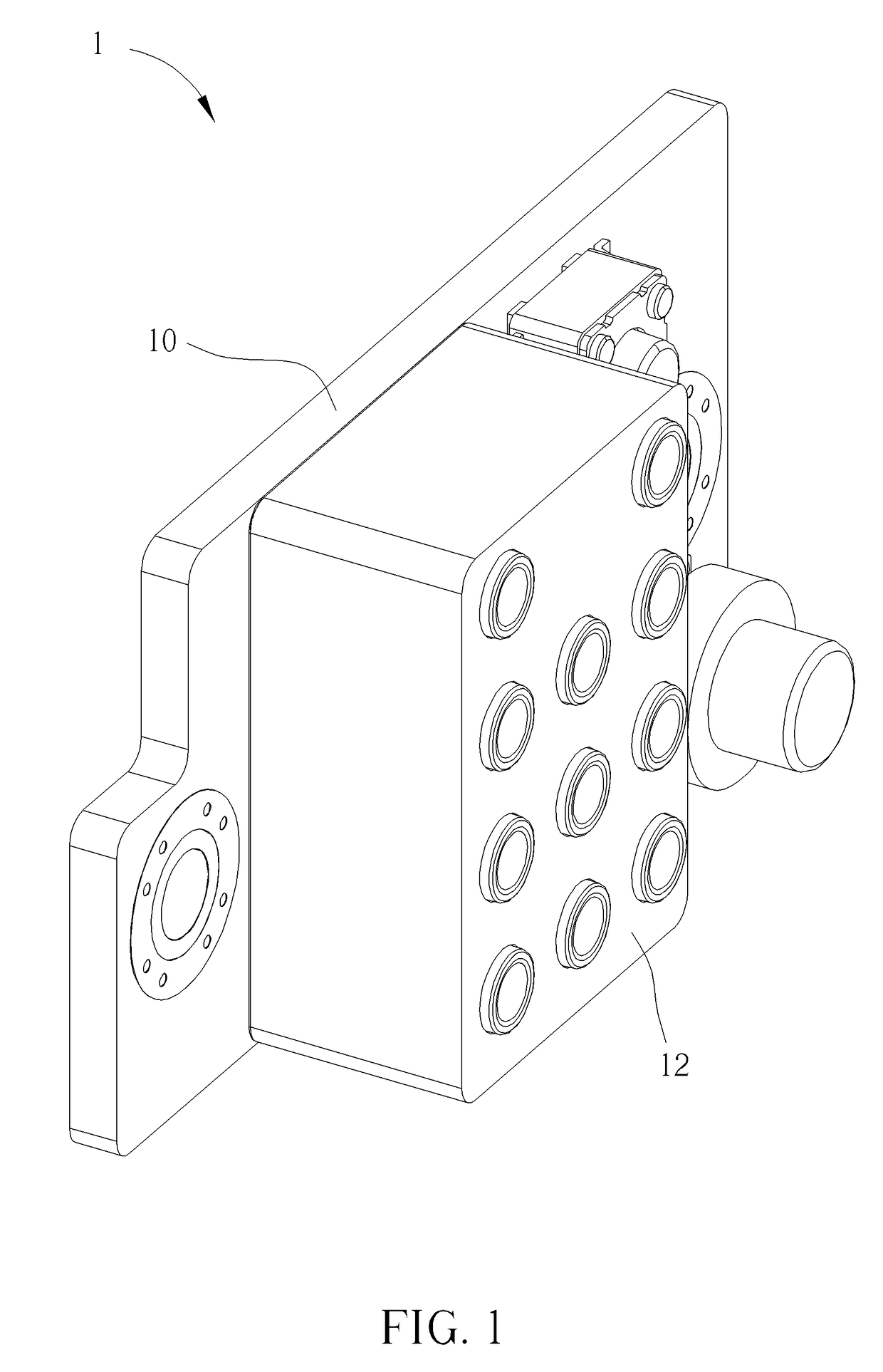
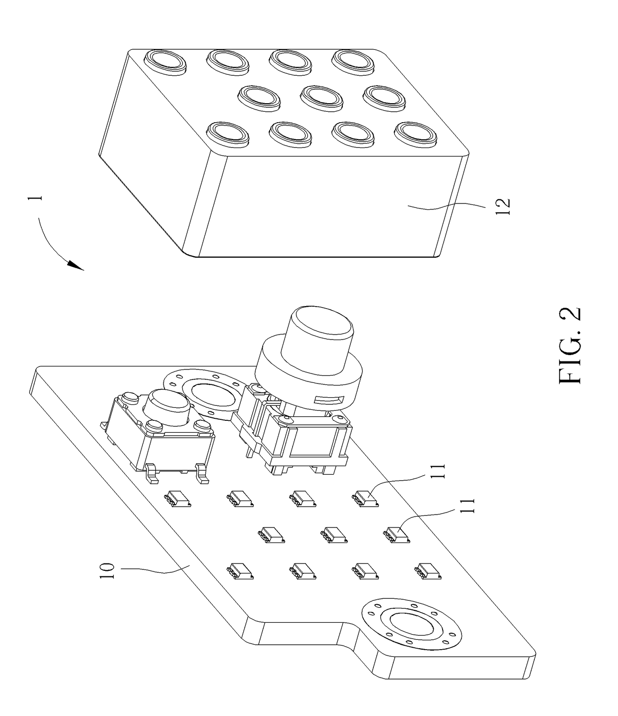
[0021]Please refer to FIG. 1 and FIG. 2. FIG. 1 is an internal structure diagram of a light emitting device 1 according to an embodiment of the present disclosure. FIG. 2 is an exploded diagram of the light emitting device 1 shown in FIG. 1 according to the embodiment of ...


PUM


Abstract

A light guiding structure includes a resilient base and a plurality of light guiding columns. A plurality of through holes is separately formed on the resilient base. The plurality of light guiding columns resiliently engages with the plurality of through holes. Each of a plurality of light emitting components is disposed on an end of each of the plurality of the light guiding columns. The light guiding structure utilizes the plurality of light guiding columns for guiding the light transmitted from the plurality of light emitting components and further utilizes the resilient base for allowing the light transmitted from one of the plurality of light emitting components to pass through the corresponding light guiding column only. Therefore, the light transmitted from the plurality of light emitting components can be guided to a correct position, which effectively reduces human misjudgment.

Description

BACKGROUND OF THE INVENTION[0001]1. Field of the Invention[0002]The present disclosure relates to a light guiding structure and a light emitting device, and more particularly, to a light guiding structure for guiding light transmitted from a plurality of light emitting components, and a light emitting device therewith.[0003]2. Description of the Prior Art[0004]A light guiding structure is usually utilized for guiding light transmitted from a light emitting component to a panel module of an electronic device, so that users can judge a current operational condition of the electronic device by observing a position and a color of the light displayed on the panel module. However, the light emitting component can be considered as a point light source due to an optical characteristic of the light emitting component. That is, the light transmitted from the light emitting component travels radially instead of unidirectional travel. Therefore, the light transmitted from the light emitting com...

Claims


Application Information

Patent Timeline
IPC IPC(8): F21V8/00F21V17/06F21V17/10F21K99/00
CPCG02B6/0008F21V17/101F21V17/06F21K9/52G02B6/0078G02B6/0088G02B6/0091F21K9/61F21V5/007F21W2111/00F21Y2113/10
Inventor GUO, ZHI MINGLI, CHEN-YUWANG, JUN HAOZHU, CHONG-XING
Owner WISTRON CORP
Why Eureka
Try Eureka