Developer supply container and developer supplying apparatus
a technology for supplying containers and supplying equipment, applied in electrographic process equipment, instruments, optics, etc., can solve the problem of large size of supply containers, and achieve the effect of stable discharg
- Summary
- Abstract
- Description
- Claims
- Application Information
AI Technical Summary
Benefits of technology
Problems solved by technology
Method used
Image

Examples
embodiment 1
[0031]First, basic structures of an image forming apparatus will be described, and then, a developer supplying system, that is, a developer replenishing apparatus and a supply container used in the image forming apparatus will be described.
(Image Forming Apparatus)
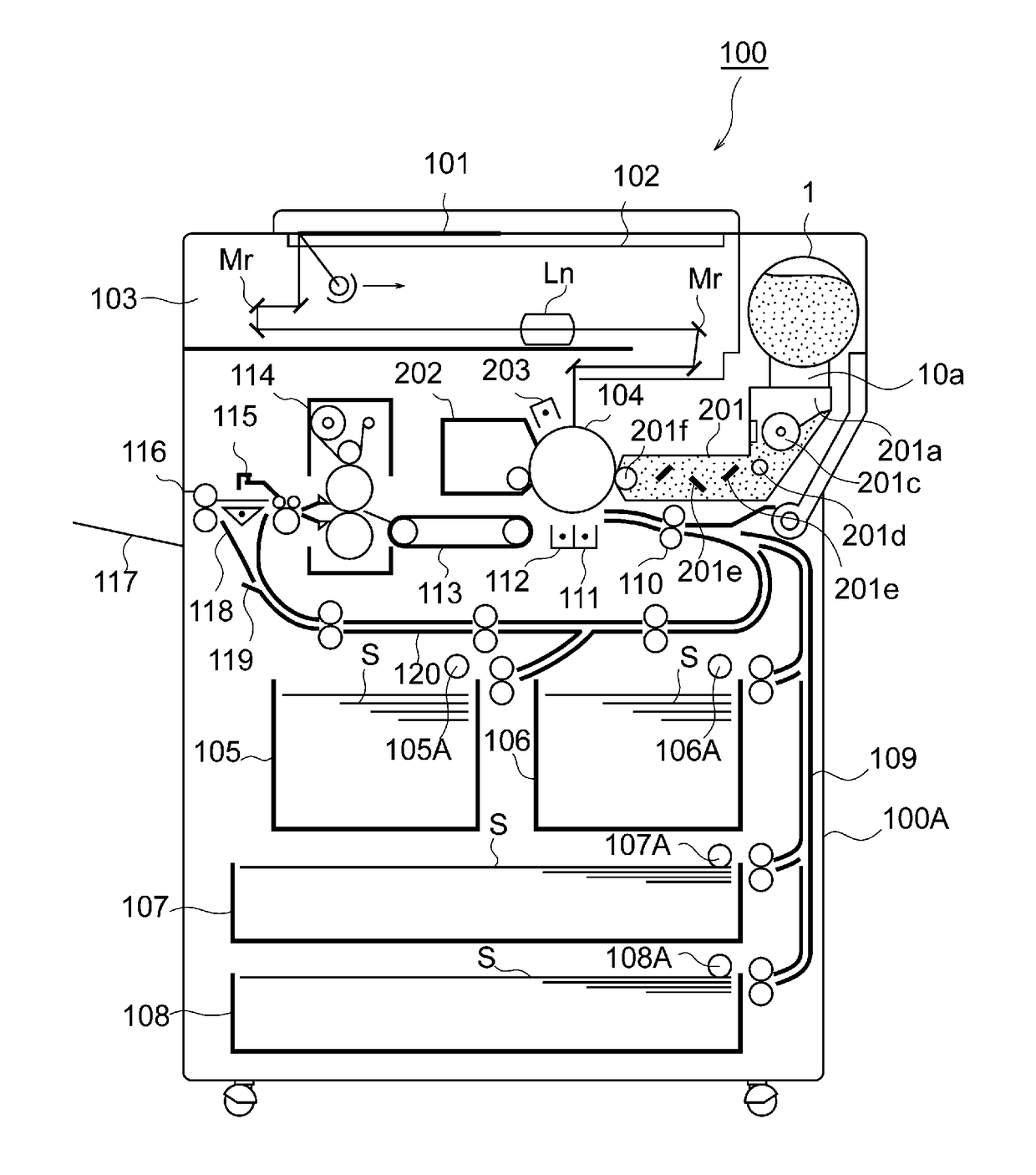
[0032]FIG. 1 is a sectional view of an image forming apparatus 100 according to Embodiment 1 The image forming apparatus 100 is an example of an electrophotographic type copying machine (electrophotographic image forming apparatus) and is provided with a supplying device 201 to which a supply container 1 (so-called toner cartridge) is detachably mountable (demountable). The supply container 1 as the “developer supply container” is detachably mountable to the supplying device 201 as “developer supplying apparatus”, that is, detachably mountable to a main assembly 100A of the image forming apparatus. Therefore, when the supply container 1 and / or the supplying device 201 is in the form of a cartridge, the cartridge is detacha...
embodiment 2
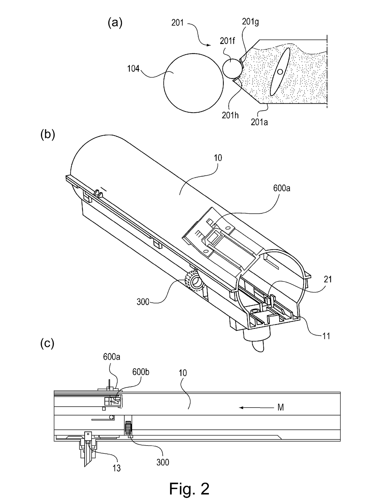
[0150]Part (a) of FIG. 18 is a perspective view of the flange portion 4 of the supply container 1 according to Embodiment 2, as seen from the accommodating portion 2. Part (b) of FIG. 18 is a sectional view of the flange portion 4. The supply container 1 of Embodiment 2 is different from the supply container 1 of Embodiment 1 in the partition 20, the fluid communication path 20a and the feeding member 6.
[0151]As shown in part (b) of FIG. 18, the flange portion 4 is provided with a partition 20 as the suppressing portion as a partition between the pump portion 3a and the accommodating portion 2. The partition 20 is provided with an annular rib 20b substantially at the center on the accommodating portion 2 side. The annular rib 20b is provided with a shaft sealing member 22 on the inside surface of the annular rib 20b. Inside of the annular rib 20b, there is provided a fluid communication path 20a. The fluid communication path 20a permits air flow the through together with the pump po...
modified example
[0177]FIG. 21 is an enlargement perspective view of the feeding member 6 of the supply container 1 according to a modified example of Embodiment 2. In the description of this embodiment, the same reference numerals as in Embodiment 2 are assigned to the elements having the same structures and functions in this embodiment, and the detailed description thereof is omitted for simplicity. As shown in FIG. 21, with the supply container 1 of the modified example, the partition 20 is formed on the feeding member 6, and the partition 20 as the suppressing portion is integral with the opening 7e of the regulating portion 7. The partition 20 is mounted on the regulating portion 7. Therefore, the inside of the pump portion 3a is in fluid communication with the storage portion 4d through the opening 7e, the fluid communication path 7g and the storage portion opening 7f. The outer diameter of the partition 20 (the outer diameter of the regulating portion 7) and the inner diameter of the discharg...
PUM
 Abstract
Description
Claims
Application Information
 - Generate Ideas
- Intellectual Property
- Life Sciences
- Materials
- Tech Scout
- Unparalleled Data Quality
- Higher Quality Content
- 60% Fewer Hallucinations
Browse by: Latest US Patents, China's latest patents, Technical Efficacy Thesaurus, Application Domain, Technology Topic, Popular Technical Reports.
© 2025 PatSnap. All rights reserved.Legal|Privacy policy|Modern Slavery Act Transparency Statement|Sitemap|About US| Contact US: help@patsnap.com