Energy storage apparatus

Active Publication Date: 2017-08-24
GS YUASA INT LTD +1
View PDF1 Cites 10 Cited by
  • Summary
  • Abstract
  • Description
  • Claims
  • Application Information

AI Technical Summary

Benefits of technology

[0009]An object of the present invention is to provide an energy storage apparatus where

Problems solved by technology

In this case, in the bus bar which connects the electrode terminal of the flat secondary battery on one side and the electrode terminal of the flat secondary battery on the other side to each other, a stress caused by a change in the above-mentioned distance is concentrated on a connecting portion between the electrode terminals and hence, the connecting portion is liable to be damaged.
That is, when a difference is g

Method used


Image

  • Energy storage apparatus
  • Energy storage apparatus
  • Energy storage apparatus

Examples


Embodiment Construction

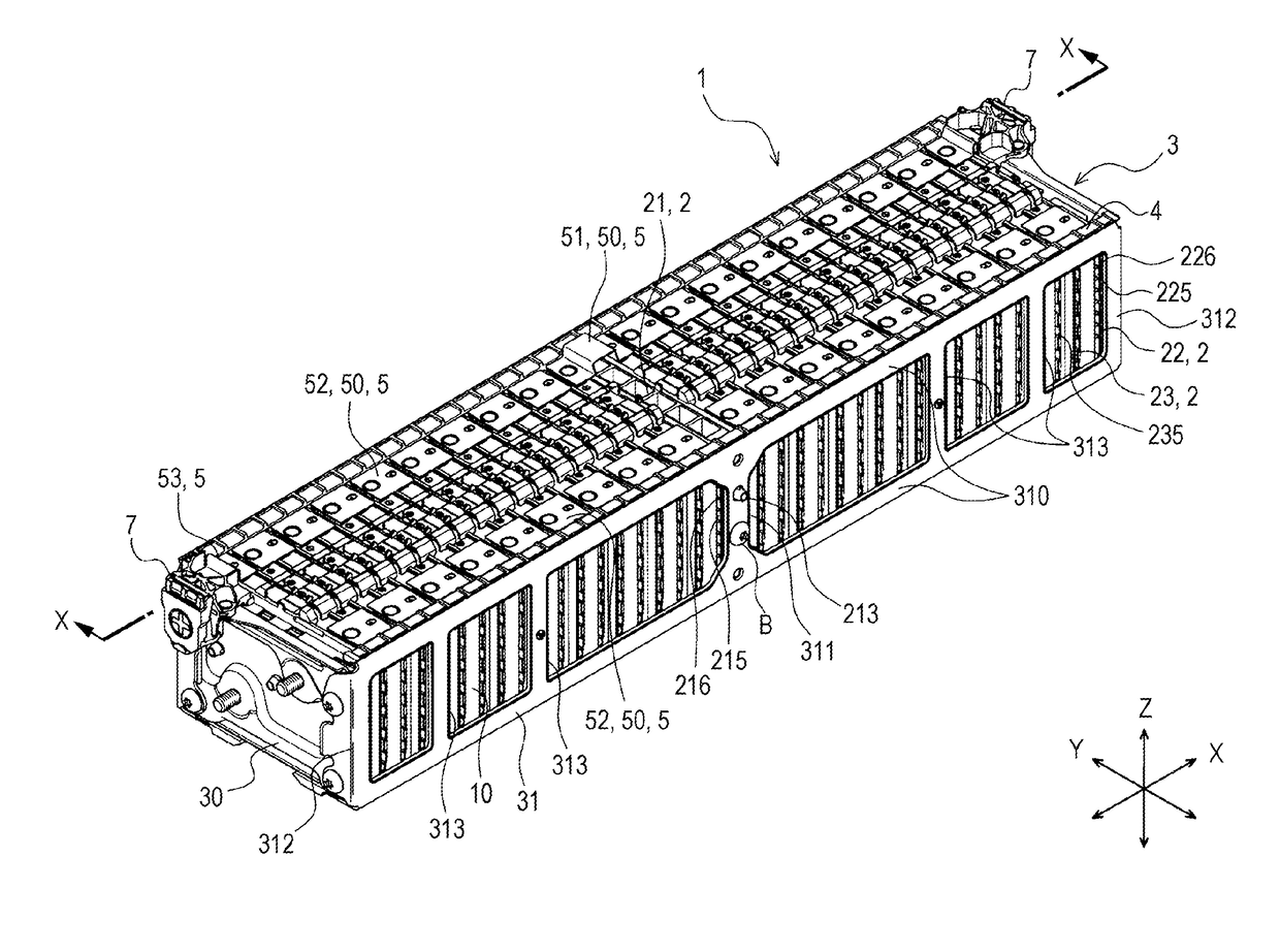
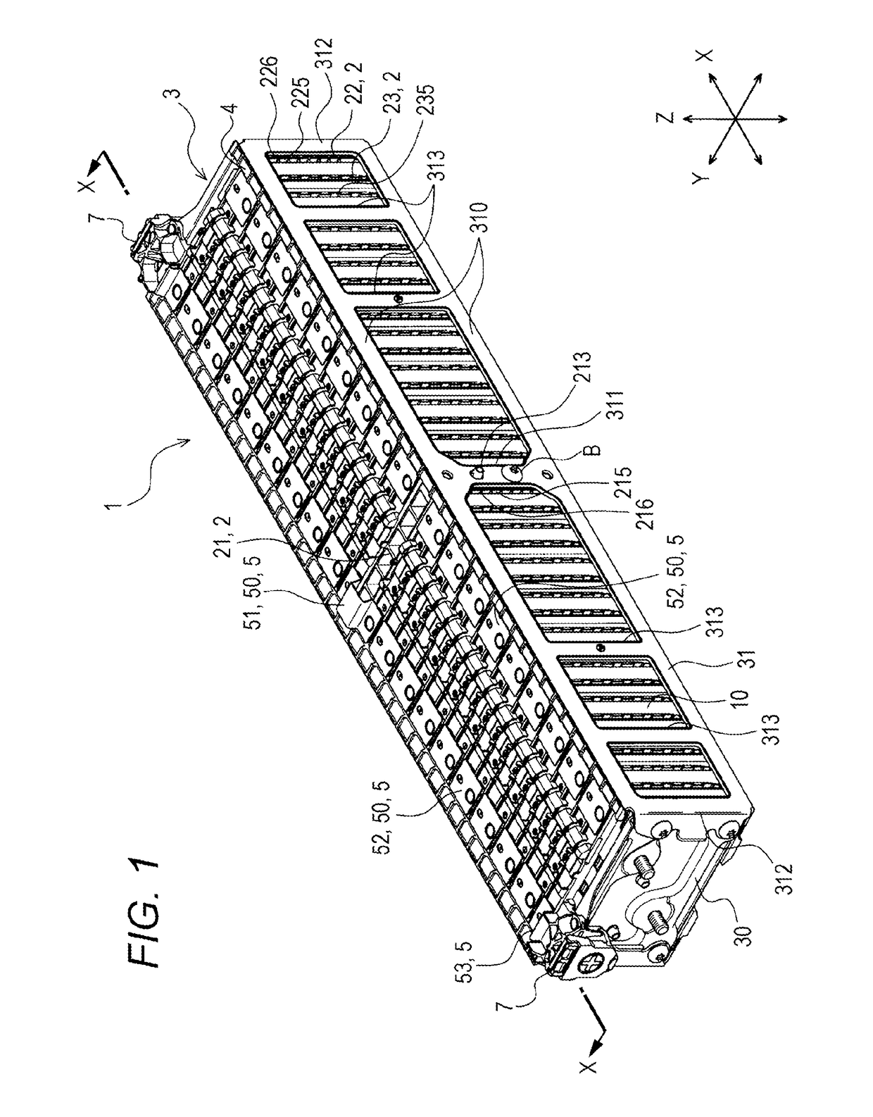
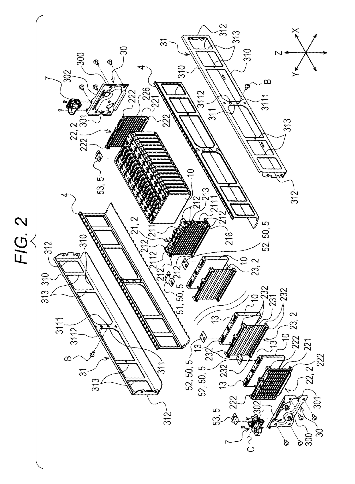
[0036]According to an aspect of the present invention, there is provided an energy storage apparatus which including:

[0037]a plurality of energy storage devices which respectively have an external terminal and are arranged in a row in a first direction;

[0038]an adjacent member disposed between the energy storage devices disposed adjacently to each other in the first direction;

[0039]a holder provided for holding the plurality of energy storage devices and the adjacent member by surrounding a periphery of the plurality of energy storage devices and the adjacent member, wherein the adjacent member is fixed to the holder; and

[0040]a bus bar which is configured to make the external terminals of the energy storage devices disposed on both sides of the adjacent member among the plurality of energy storage devices conductive with each other wherein

[0041]the bus bar includes:

[0042]a first connecting portion connected to one external terminal which is made conductive by the bus bar;

[0043]a se...


PUM


Abstract

Provided is an energy storage apparatus which includes: a plurality of energy storage devices which respectively have an external terminal and are arranged in a row in a first direction; an adjacent member disposed between the energy storage devices disposed adjacently to each other in the first direction; and a bus bar which connects the external terminals of the energy storage devices disposed on both sides of the adjacent member to each other. The bus bar includes: a first connecting portion connected to one external terminal; a second connecting portion connected to the other external terminal; and a portion which extends in a projecting manner in a direction away from the adjacent member in a second direction orthogonal to the first direction or a portion which extends in a recessed manner in a direction that the portion approaches the adjacent member in the second direction in a state where the portion is spaced-apart from the adjacent member between the first connecting portion and the second connecting portion.

Description

CROSS-REFERENCE TO RELATED APPLICATIONS[0001]This application claims the benefit of Japanese patent application No. 2016-030226 filed on Feb. 19, 2016 which is incorporated by reference.FIELD[0002]The present invention relates to an energy storage apparatus which includes energy storage devices having external terminals, and bus bars connected to the external terminals.BACKGROUND[0003]Conventionally, there has been known a battery system which includes a plurality of flat secondary batteries (see JP 2014-44884 A). To be more specific, the battery system includes: the plurality of flat secondary batteries respectively having electrode terminals and are stacked in a thickness direction; bus bars each connecting the electrode terminals of the flat secondary batteries disposed adjacently to each other; and intermediate reinforcing plates each disposed between the flat secondary batteries.[0004]The bus bar is a conductive member having a flat plate shape which extends straightly in a sta...

Claims


Application Information

Patent Timeline
IPC IPC(8): H01M2/30H01M2/20H01M50/209H01M50/264H01M50/505H01M50/55H01M50/553
CPCH01M2/202H01M2/30H01M50/505H01M50/553H01M50/209H01M50/55H01M50/264H01G11/10H01G11/76H01G11/82Y02E60/10Y02E60/13
Inventor YUASA, EIJISHIBUYA, KENTARO
Owner GS YUASA INT LTD
Why Eureka
Try Eureka