Electronic beacon reader system and method

a technology of electronic beacons and reader systems, applied in the field of electronic beacon reader systems and methods, can solve the problems of affecting the granularity of the system deploying near-field sensors, affecting the speed of deployment, and affecting the accuracy of the system

Active Publication Date: 2017-08-24
ELECTRONICS BEACONS SYST LLC
View PDF0 Cites 15 Cited by
  • Summary
  • Abstract
  • Description
  • Claims
  • Application Information

AI Technical Summary

Benefits of technology

[0009]The present invention covers a system and method for deploying and reading data from electronic beacons or radio frequency transmitting devices to create an Internet of Things or smart environment. An embodiment of a beacon reader of the present invention is a network-connected device including a computational circuit board; a Bluetooth or radio frequency module; and a network connectivity module. The beacon reader is further configured to run software designed to assign unique identifying information to Bluetooth beacons or radio frequency sensors; scan for and collect data from Bluetooth beacons or sensors and / or other radio frequency-based sensors; trigger proximity and / or data driven events; and send data to a network-connected database to be used in a user interface. The beacon readers and beacons or sensors of the present invention can be powered by batteries or USB-ports, allowing for added versatility of the system. Each beacon reader can connect to the internet via an Ethernet port, Wi-Fi, or an embedded cell or data chip, which allows the system to be deployed and to report data to a web portal nearly anywhere.

Problems solved by technology

These technologies involve extensive installation to integrate within existing infrastructures as they relate to a specific industries or use-cases, and thus they can be expensive to set-up and use.
Considerable installation and integration into building infrastructure, such as physical installation into walls and / or doors, access to power lines, access to network lines, etc., is required for such a system, prohibiting it from being quickly deployed and making it costly.
Additionally, systems deploying near-field sensors lose a level of granularity because near-field sensors require physical touch or near-touching points to create or trigger events.

Method used


Image

  • Electronic beacon reader system and method
  • Electronic beacon reader system and method
  • Electronic beacon reader system and method

Examples


Embodiment Construction

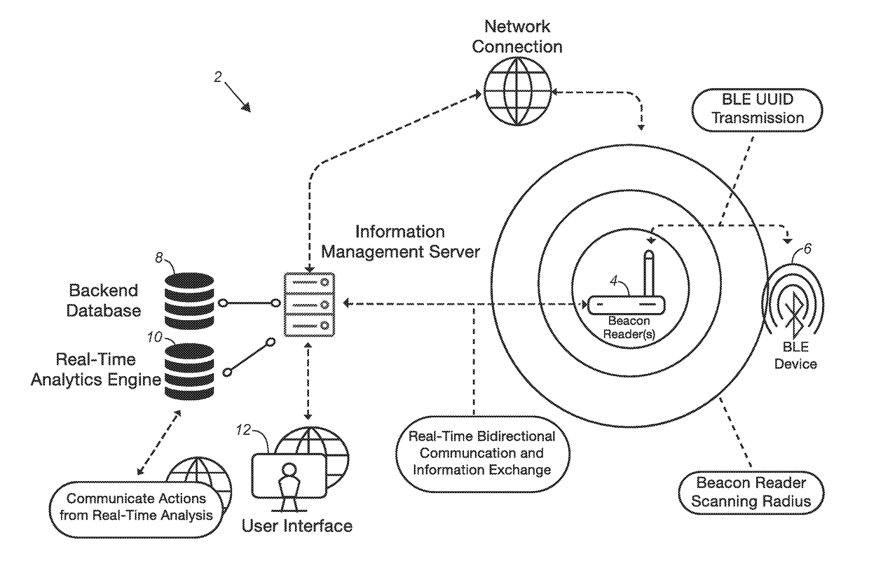
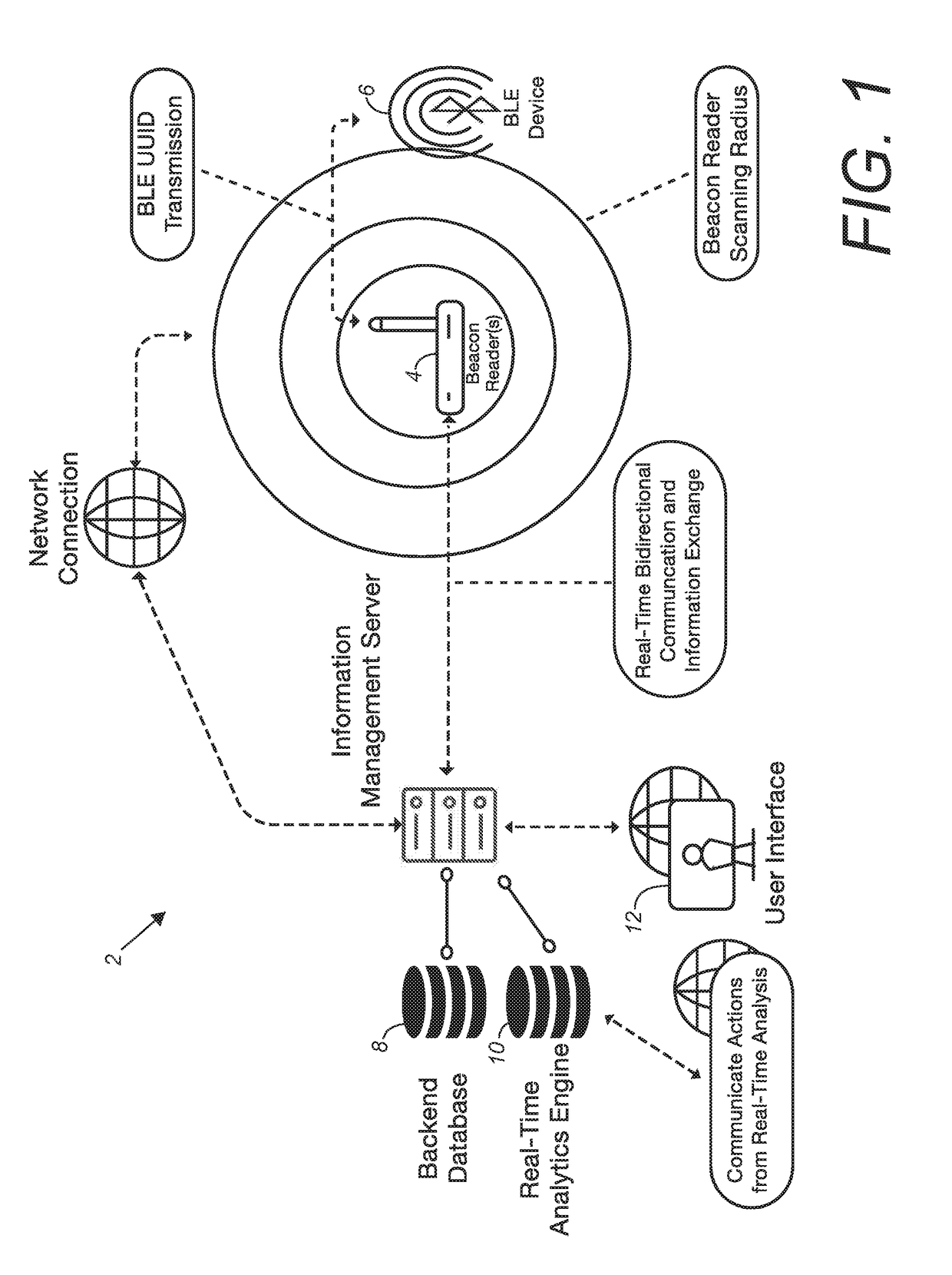
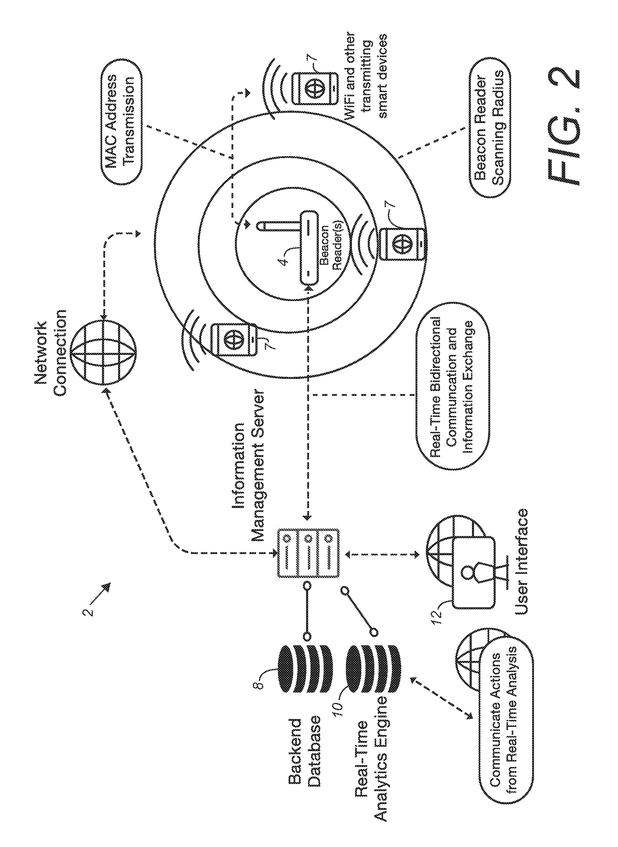
I. Introduction and Environment

[0014]As required, detailed aspects of the present invention are disclosed herein, however, it is to be understood that the disclosed aspects are merely exemplary of the invention, which may be embodied in various forms. Therefore, specific structural and functional details disclosed herein are not to be interpreted as limiting, but merely as a basis for the claims and as a representative basis for teaching one skilled in the art how to variously employ the present invention in virtually any appropriately detailed structure.

[0015]Certain terminology will be used in the following description for convenience in reference only and will not be limiting. For example, up, down, front, back, right, and left refer to the invention as orientated in the view being referred to. The words, “inwardly” and “outwardly” refer to directions toward and away from, respectively, the geometric center of the aspect being described and designated parts thereof. Forwardly and...


PUM


Abstract

A system and method for deploying and reading data from sensors or electronic beacons to create a sensor rich, Internet of Things environment. A beacon reader embodying an aspect of the present invention includes a computing chip, a Bluetooth or other radio frequency (RF) module, and an internet connectivity module. The beacon reader is configured for use with Bluetooth beacons or other RF transmitting devices or sensors, Wi-Fi transmitting devices, a network-connected database, a real time analytics engine configured for performing real time analysis and allowing bidirectional communication and information exchange, a network-connected computing device having a display, and a user interface. The beacon reader is configured to assign identifying information to the Bluetooth beacons or other RF transmitting devices; scan for and collect data from the beacons or transmitting devices; trigger proximity and / or data driven events; and send data to the database viewable in the user interface.

Description

CROSS-REFERENCE TO RELATED APPLICATION[0001]This application claims priority in U.S. Provisional Patent Application No. 62 / 297,499, filed Feb. 19, 2016, which is incorporated herein by reference.BACKGROUND OF THE INVENTION[0002]1. Field of the Invention[0003]The present invention relates to a system and method for creating a connected “Internet of Things” environment or infrastructure via the use of Bluetooth beacons or radio frequency sensors. More particularly, the present invention relates to assigning identifiers to Bluetooth beacons or radio frequency sensors which each represent a person, place, or thing; collecting data based on proximity to the invention; and sending the data to a network-connected database.[0004]2. Description of the Related Art[0005]Currently, most technologies used to create connected, sensor rich environments utilize near-field radio frequency sensors, which require integration into existing infrastructures and Internet access points. These technologies ...

Claims


Application Information

Patent Timeline
Patent Type & Authority Applications(United States)
IPC IPC(8): H04W4/02H04W8/00H04W4/00H04L29/08G06K17/00H04W4/70H04W4/80
CPCH04W4/023H04L67/12G06K2017/0045H04W4/008H04W8/005G06K17/0022H04W4/70H04W4/80H04W84/18
Inventor RUIZ, JONATHAN A.WATERS, BRENDAN W.WATERS, WILLIAM G.
Owner ELECTRONICS BEACONS SYST LLC
Why Eureka
Try Eureka