Vibration motor

Inactive Publication Date: 2017-08-31
SANYO SEIMITSU
View PDF6 Cites 4 Cited by
  • Summary
  • Abstract
  • Description
  • Claims
  • Application Information

AI Technical Summary

Benefits of technology

[0006]The above preferred embodiment of the present in

Problems solved by technology

Therefore, a high bearing rigidity cannot be achieved, making

Method used


Image

  • Vibration motor
  • Vibration motor
  • Vibration motor

Examples


Example

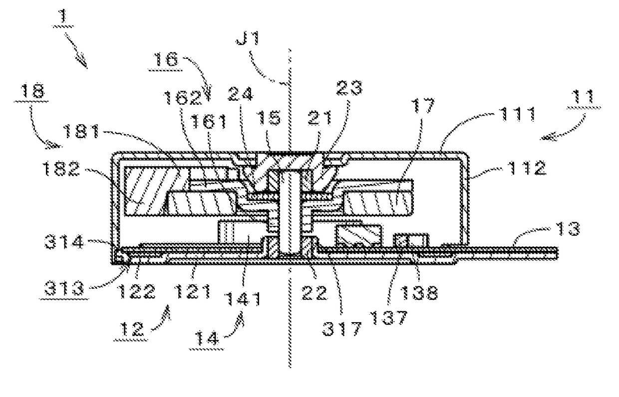
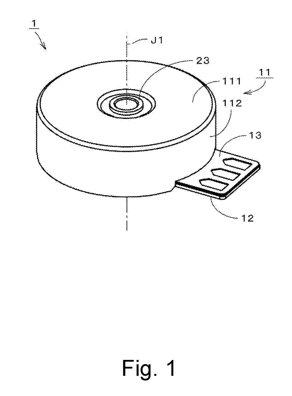
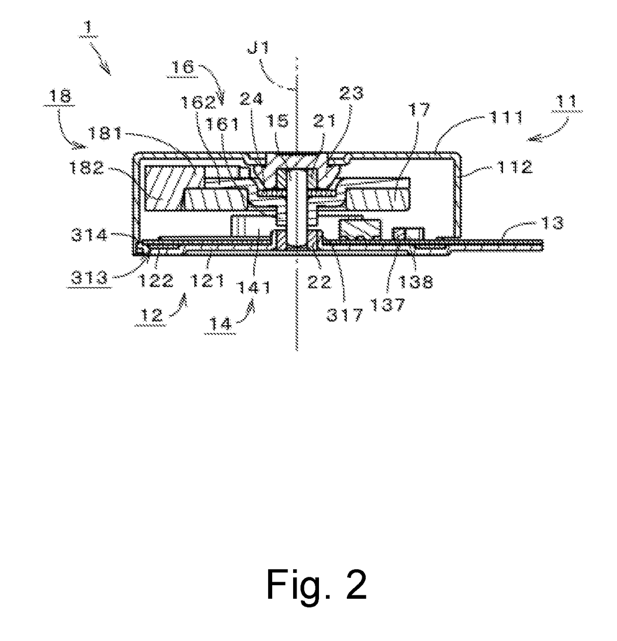
[0021]It is assumed herein that a vertical direction is defined as a direction in which a central axis J1 of a vibration motor 1 extends, and that an upper side and a lower side along the central axis J1 in FIG. 2 are referred to simply as an upper side and a lower side, respectively. It should be noted, however, that the above definitions of the vertical direction and the upper and lower sides are not meant to indicate relative positions or directions of different members or portions when those members or portions are actually installed in a device. It is also assumed herein that a direction parallel to the central axis J1 is referred to as the vertical direction. Further, it is assumed herein that radial directions centered on the central axis J1 are simply referred to by the term “radial direction”, “radial”, or “radially”, and that a circumferential direction about the central axis J1 is simply referred to by the term “circumferential direction”, “circumferential”, or “circumfer...


PUM


Abstract

A vibration motor includes a base portion arranged to extend perpendicularly to a central axis extending in a vertical direction; a cover portion arranged above the base portion, and fixed to an outer edge portion of the base portion; a lower bearing portion fixed to the base portion; an upper bearing portion fixed to the cover portion; a shaft arranged to extend along the central axis, and having a lower end portion and an upper end portion rotatably supported by the lower bearing portion and the upper bearing portion, respectively; a rotor holder attached to the shaft; a magnet portion including a plurality of magnetic poles, and attached to the rotor holder; an eccentric weight attached to the rotor holder; a circuit board arranged above the base portion; and a coil portion attached onto the circuit board, and arranged vertically opposite to the magnet portion with a space therebetween.

Description

CROSS REFERENCE TO RELATED APPLICATIONS[0001]This application claims the benefit of priority to Japanese Patent Application No. 2016-035598 filed on Feb. 26, 2016. The entire contents of this application are hereby incorporated herein by reference.BACKGROUND OF THE INVENTION1. Field of the Invention[0002]The present invention relates to a vibration motor.2. Description of the Related Art[0003]Brushless vibration motors in the shape of a thin coin have often been used as silent notification devices in mobile communication apparatuses or the like, or for other purposes. In a vibration motor illustrated in FIG. 12 of JP-A 2004-357404, for example, a shaft support portion 11a is arranged to project upward from a central portion of a yoke bracket 111 to assume the shape of a burr, and an oil-impregnated sintered bearing 7 is housed in the shaft support portion 11a. An eccentric rotor R4 is rotatably attached to the oil-impregnated sintered bearing 7 through a shaft 22.[0004]In the vibrat...

Claims


Application Information

Patent Timeline
IPC IPC(8): B06B1/16H02K3/28H02K11/30H02K5/04H02K7/08H02K11/00
CPCB06B1/16H02K7/08H02K3/28H02K11/30H02K5/04H02K11/0094H02K7/063H02K7/083H02K7/09H02K2211/03
Inventor MORI, ZENDIMURATA, MITSURU
Owner SANYO SEIMITSU
Why Eureka
Try Eureka