Spindle motor

a spindle motor and spindle body technology, applied in the field of spindle motors, can solve the problems of reducing the amount of lubricating fluid, affecting the performance and life of the spindle motor, and inevitably weakening the bearing rigidity, so as to enhance the bearing rigidity and prevent leakage. , the effect of enhancing the bearing rigidity

Inactive Publication Date: 2014-07-03
SAMSUNG ELECTRO MECHANICS CO LTD
View PDF7 Cites 1 Cited by
  • Summary
  • Abstract
  • Description
  • Claims
  • Application Information

AI Technical Summary

Benefits of technology

[0013]An aspect of the present invention provides a spindle motor having enhanced rigidity, having enhanced bearing rigidity in spite of being small and thin, able to prevent leakage of a lubricating fluid, and having a lengthened lifespan.

Problems solved by technology

Spindle motors are required to have high capacity and to be thinned, and as spindle motors are thinned and reduced in size, bearing rigidity is inevitably weakened.
Also, a lubricating fluid injected into a fluid dynamic bearing assembly may be leaked to the outside thereof, or an amount of the lubricating fluid may be reduced due to evaporation, reducing pressure generation in a fluid dynamic bearing and leading to a problem with performance and a life span of the spindle motor.

Method used


Image

  • Spindle motor
  • Spindle motor
  • Spindle motor

Examples


first embodiment

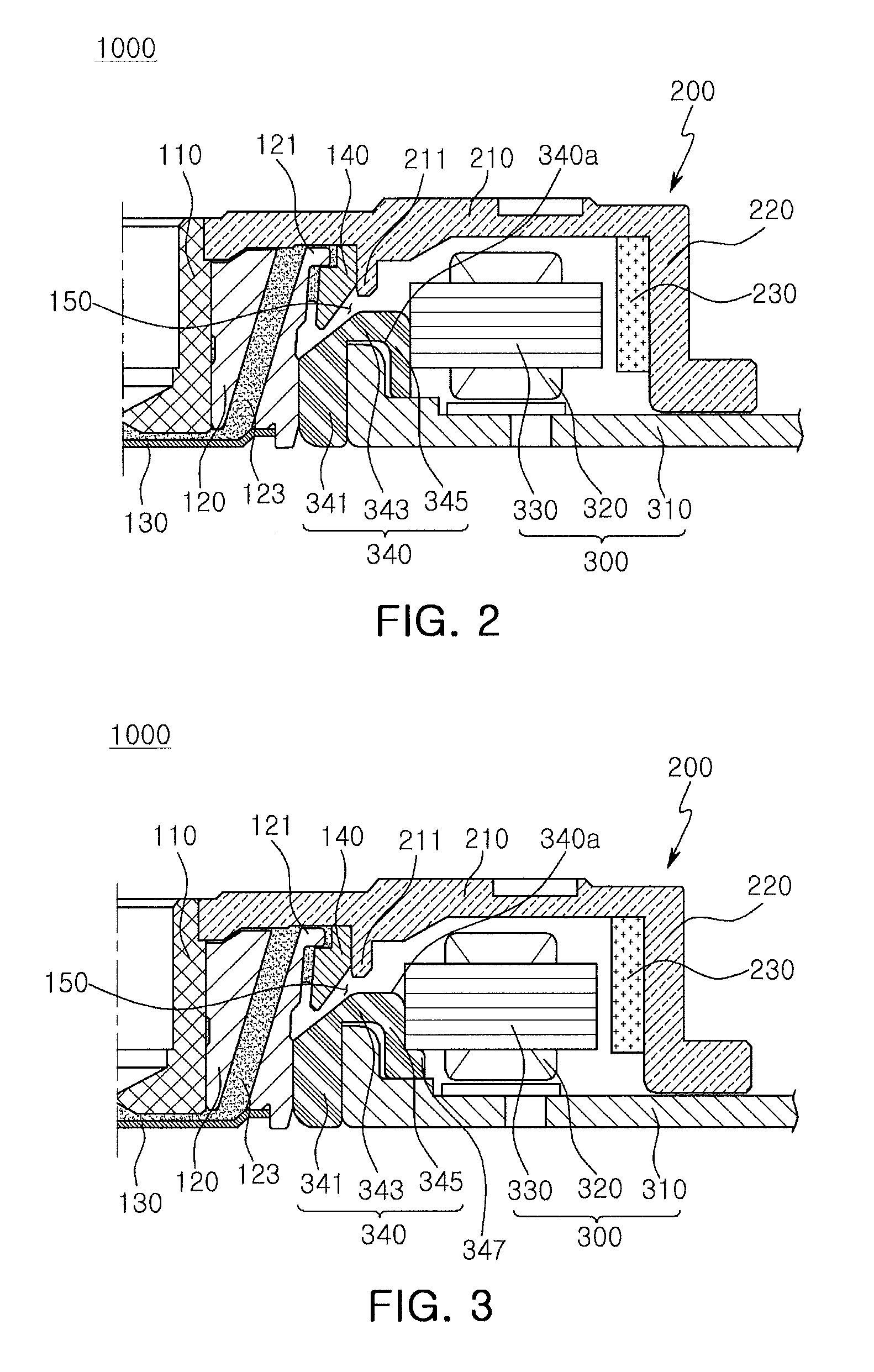
[0058]FIG. 3 is a cross-sectional view of half of the spindle motor illustrating a modification of a stator holder provided in the spindle motor according to the present invention;

[0059]FIG. 4 is a cross-sectional view of half of the spindle motor illustrating another modification of a stator holder provided in the spindle motor according to the first embodiment of the present invention. FIG. 5 is a cross-sectional view of half of the spindle motor in which a stator holder and a cover plate are integrally formed according to the first embodiment of the present invention.

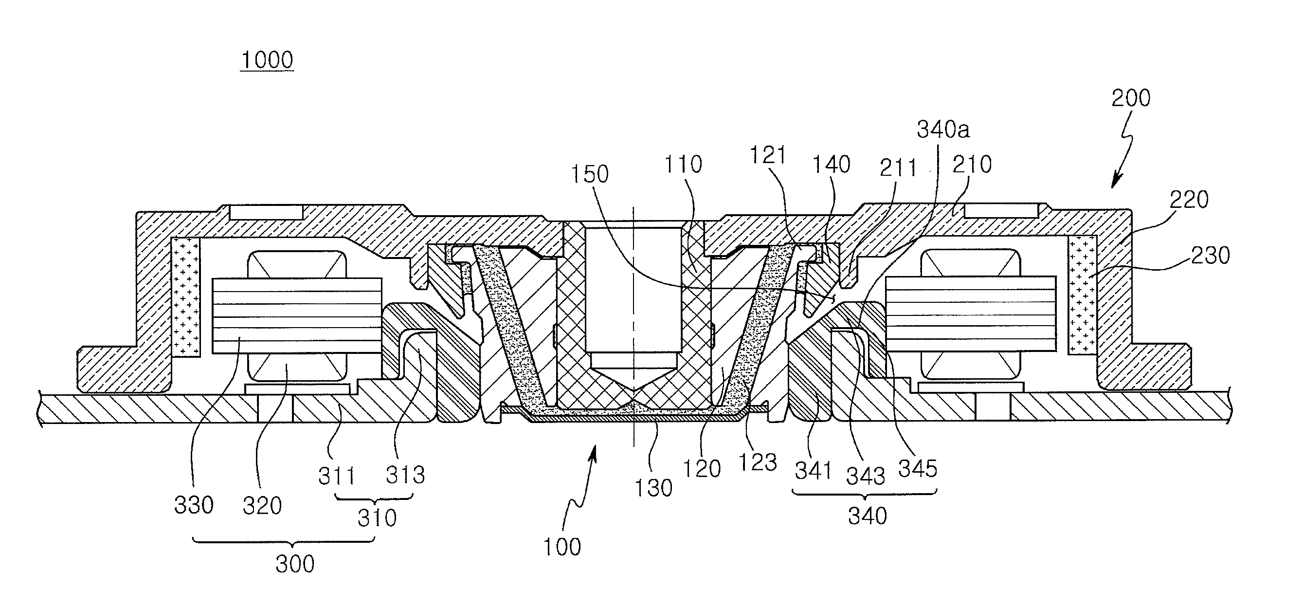
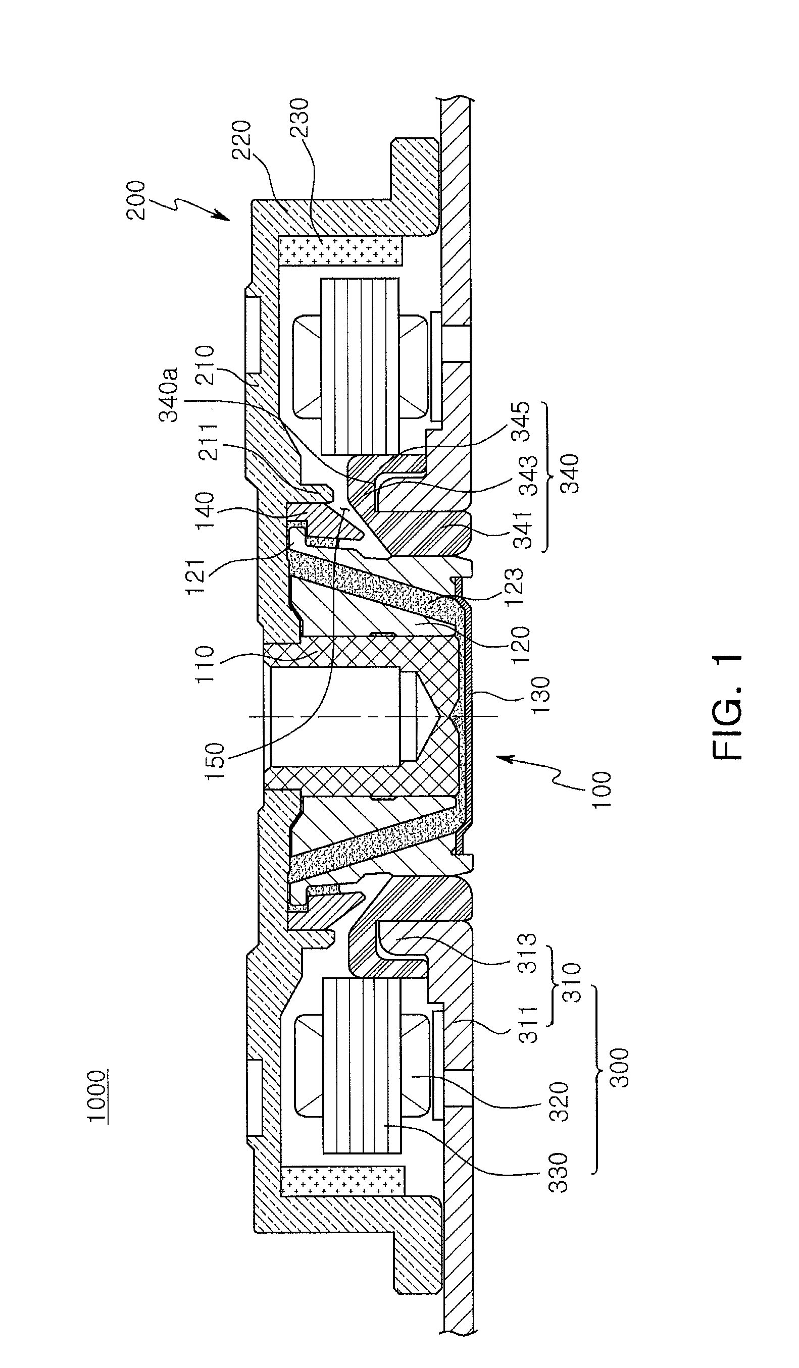
[0060]Referring to FIGS. 1 through 5, a spindle motor 1000 according to a first embodiment of the present invention may include a fluid dynamic bearing assembly 100, a stator 300 as a fixed member, and a rotor 200 as a rotating member.

[0061]First, referring to definitions of directional terms, an axial direction may refer to a vertical direction based on a shaft 110, and an outer and inner radial direction may refer ...

second embodiment

[0120]Also, in the spindle motor 2000 according to the present invention, a fluid-air interface of a lubricating fluid may be formed to seal a lubricating fluid between stopper portion 140 and the connection portion 343 of the stator holder 340.

[0121]Here, a lower surface of the stopper portion 140 and an upper surface of the connection portion 343 may face one another, and in this case, the lower surface of the stopper portion 140 and the upper surface of the connection portion 343 may be tapered.

[0122]Namely, the lower surface of the stopper portion 140 and the upper surface of the connection portion 343 may be sloped upwardly and outwardly in the radial direction, so a lubricating fluid may be sealed between the lower surface of the stopper portion 140 and the upper surface of the connection portion 343.

[0123]Thus, a storage space of the lubricating fluid can be sufficiently secured.

[0124]While the spindle motor is being driven, the lubricating fluid may be gradually reduced due ...


PUM


Abstract

There is provided a spindle motor including: a sleeve rotatably supporting a shaft; a rotor coupled to an upper end of the shaft and rotating in conjunction with the shaft; a stopper portion coupled to a main wall portion protruded from one surface of the rotor and facing an outer circumferential surface of the sleeve; a stator holder having a fixed portion coupled to an outer circumferential surface of the sleeve, an installation portion to which a core having a coil wound therearound is fixed, and a connection portion connecting an upper end of the fixed portion and an upper end of the installation portion; and a base member fixedly coupled to the stator holder.

Description

CROSS-REFERENCE TO RELATED APPLICATIONS[0001]This application claims the priority of Korean Patent Application No. 10-2012-0155297 filed on Dec. 27, 2012, in the Korean Intellectual Property Office, the disclosure of which is incorporated herein by reference.BACKGROUND OF THE INVENTION[0002]1. Field of the Invention[0003]The present invention relates to a spindle motor.[0004]2. Description of the Related Art[0005]A hard disk drive (HDD), an information storage device, is a device for reading data stored on a disc or writing data to a disc with a read / write head.[0006]A hard disk drive requires a disc driving device for driving a disc, and a small spindle motor is used in the disc driving device.[0007]A spindle motor employs a fluid dynamic bearing assembly (or a hydrodynamic bearing assembly), in which a lubricating fluid is interposed between a shaft, a rotary member of the fluid dynamic bearing assembly, and a sleeve, a fixed member of the fluid dynamic bearing assembly, and the s...

Claims


Application Information

Patent Timeline
Patent Type & Authority Applications(United States)
IPC IPC(8): H02K5/16
CPCH02K5/163G11B19/2009H02K1/187H02K5/1675F16C17/10F16C33/10G11B19/20H02K5/173
Inventor SMIRNOV, VIATCHESLAV
Owner SAMSUNG ELECTRO MECHANICS CO LTD
Why Eureka
Try Eureka