Improved internal combustion engine with bearing cap dampening

a technology of dampening and internal combustion engine, which is applied in the direction of machines/engines, mechanical equipment, and casings, etc., can solve the problems of generating even more noise, generating noise, and generating medium to high frequency vibration in the engine structure, and achieves reasonable cost and vibration dampening

Inactive Publication Date: 2010-03-11
VOLVO LASTVAGNAR AB
View PDF5 Cites 2 Cited by
  • Summary
  • Abstract
  • Description
  • Claims
  • Application Information

AI Technical Summary

Benefits of technology

[0008]In view of the shortcomings of the above-mentioned solutions, it is desirable to provide a novel solution to dampen crankshaft

Problems solved by technology

Most of the noise created in an engine (except exhaust and ancillaries noise) originates or results in medium to high frequency vibrations in the engine's structure.
Moreover those engine excitations are strongly correlated, generating even more noise.
As they have large external surfaces and less stiffness than upper part of the cylinder block, skirts are important noise sources.
As discussed above, these vibrations generate noise, but can also be a problem in terms of the proper functioning of the bearing.
Nevertheless, this solution has the major drawback that the frame structure is rigid, so frequency of main vibrating modes increases and can generate more noise, and moreover tends to propagate bearing vibrations to the whole engine block.
Therefore, the dampening system disclosed in the above-mentioned

Method used


Image

  • Improved internal combustion engine with bearing cap dampening
  • Improved internal combustion engine with bearing cap dampening
  • Improved internal combustion engine with bearing cap dampening

Examples


first embodiment

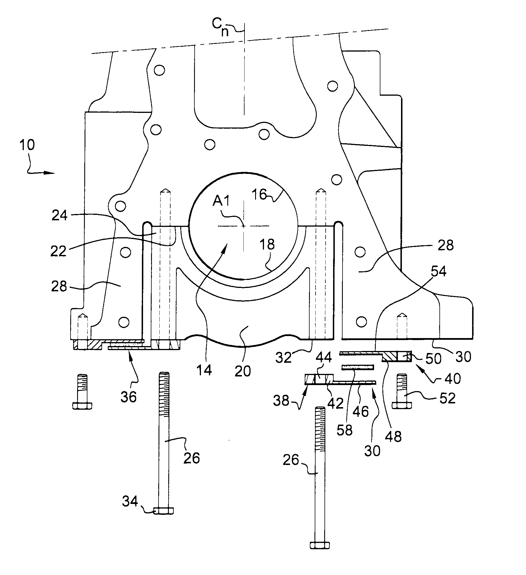
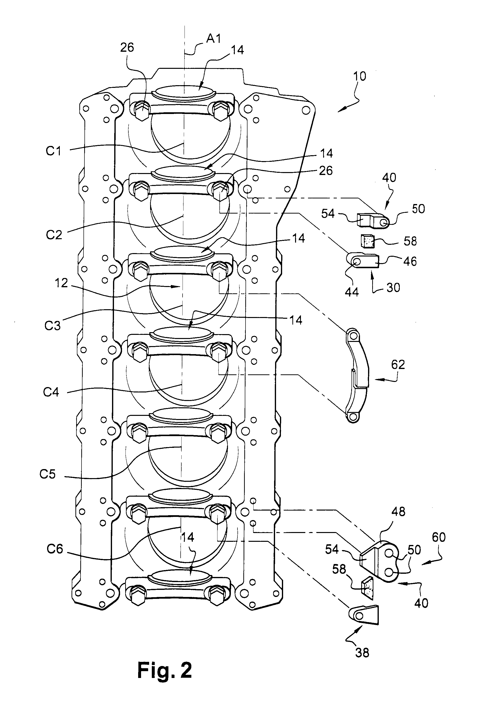
[0024]According to this first embodiment, the first 38 and second 40 support portions of the dampening structure 36 extend essentially in the transverse direction and are each fastened respectively on the bearing caps 20 and on the cylinder block by one bolt, the two bolts being transversely spaced apart. Advantageously, the bolt for fastening the first support portion 38 on the bearing cap is one of the two fixing bolts 26 which holds the bearing cap 20 on the cylinder block, so that the first support portion 38 is in fact sandwiched between the bolt's head 34 and the lower surface 32 of the bearing cap 20. The first support portion 38 has a fixing section 42 having a certain thickness and showing a through-hole 44 for the passage of the bolt 26. A horizontal flange 46, having a reduced thickness compared to the fixing section 42, extends essentially transversally from said fixing section 42 so as to be in the continuity of the lower face thereof The second support portion 40 has a...

embodiment 66

[0036]On FIG. 5 is shown very schematically a further embodiment 66 of a dampening structure for an engine according to the invention. In this further embodiment, it can be seen that the cylinder block 10 has shorter sidewalls 28 than in the previous cases. Indeed, the lower edge surface 30 of at least one of the sidewalls (in this case of both sidewalls) is located at a higher level than the lower surface 32 of the bearing caps. Therefore, in this case, the flange sections 46, 54 of each of the first 38 and second portions of the dampening structure extend along a plane P which is inclined by an angle a with respect to a horizontal plane (and in this case angled with respect to the corresponding fixing section 42, 48). The degree of inclination a will depend on the difference of height between the lower edge surface 30 of the sidewalls and of the bearing caps. It will also depend on the height of the fixing sections of the dampening structure. In the embodiment shown, the fixing se...


PUM


Abstract

An internal combustion engine has an engine block including a crankshaft which is mounted on the engine block by at least a first and a second main bearings, wherein the main bearings each include a first bearing portion and a second bearing portion, the second bearing portion being part of a bearing cap, wherein at least the first bearing cap is connected to the engine block or to the second bearing cap by at least one dampening structure, the structure including a first support portion fixed on the bearing cap, a second support portion fixed on the engine block or on an adjacent bearing cap, and a dampening portion including an elastomeric material which connects the two support portions.

Description

BACKGROUND AND SUMMARY[0001]The invention relates to the field of internal combustion engines[0002]By nature, combustion engines are noise-generating systems. The noise created by an engine can come from various sources, mainly excited by moving parts (crank-train, valve train, gears) and combustion (cylinder pressure, injection). Most of the noise created in an engine (except exhaust and ancillaries noise) originates or results in medium to high frequency vibrations in the engine's structure. Due to the fact that the engine structure is by nature very rigid in order to withstand the considerable forces developed by the engine, those vibrations propagate very easily into the whole structure. Moreover those engine excitations are strongly correlated, generating even more noise. Therefore, it is well known that there is an interest in providing means to lower internal vibrations or to counter the propagation of those vibrations inside engine structure.[0003]One main localization of vi...

Claims


Application Information

Patent Timeline
IPC IPC(8): F02F7/00
CPCF02F7/0053
Inventor SICRE, AMAURYPICHOT, FREDERIC
Owner VOLVO LASTVAGNAR AB
Why Eureka
Try Eureka