Brillouin scattering measurement method and brillouin scattering measurement system
a brillouin scattering and measurement method technology, applied in the field of fiber optic sensor technologies, can solve the problems of difficult to determine difficult to measure the true frequency shift, and few conventional reports on botdr that demonstrate high spatial resolution, and achieve excellent spatial resolution
- Summary
- Abstract
- Description
- Claims
- Application Information
AI Technical Summary
Benefits of technology
Problems solved by technology
Method used
Image

Examples
embodiment 1
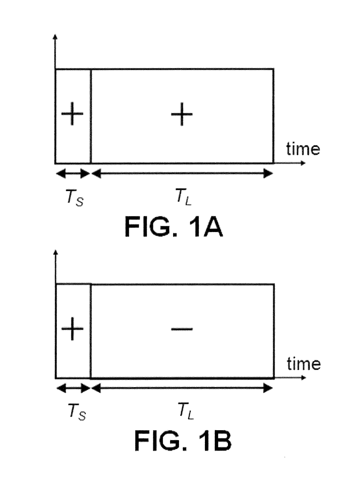
[0028]A Brillouin scattering measurement system and a Brillouin scattering measurement method according to Embodiment 1 of the present invention will be described hereinafter with reference to the drawings. FIGS. 1A and 1B shows electric signal waveforms of optical pulse probes used in the Brillouin scattering measurement system, in which the vertical axis represents the levels of the optical pulse probes and the horizontal axis represents time. The pulse probes each are composed of a short optical pulse and an adjacent long optical pulse. These pulses have durations Ts and TL (TsL), respectively. Note that the symbol “++” in FIG. 1A means that the pulses have the same phase in the sections of the durations Ts and TL, i.e., FIG. 1A is schematic diagram of the phase modulation of zero phase shift. The pulse probe with zero phase modulation is hereinafter referred to as “optical pulse pair A”. And the symbol “+−” in FIG. 1B means that the pulses have a phases difference by n (180 degr...
embodiment 2
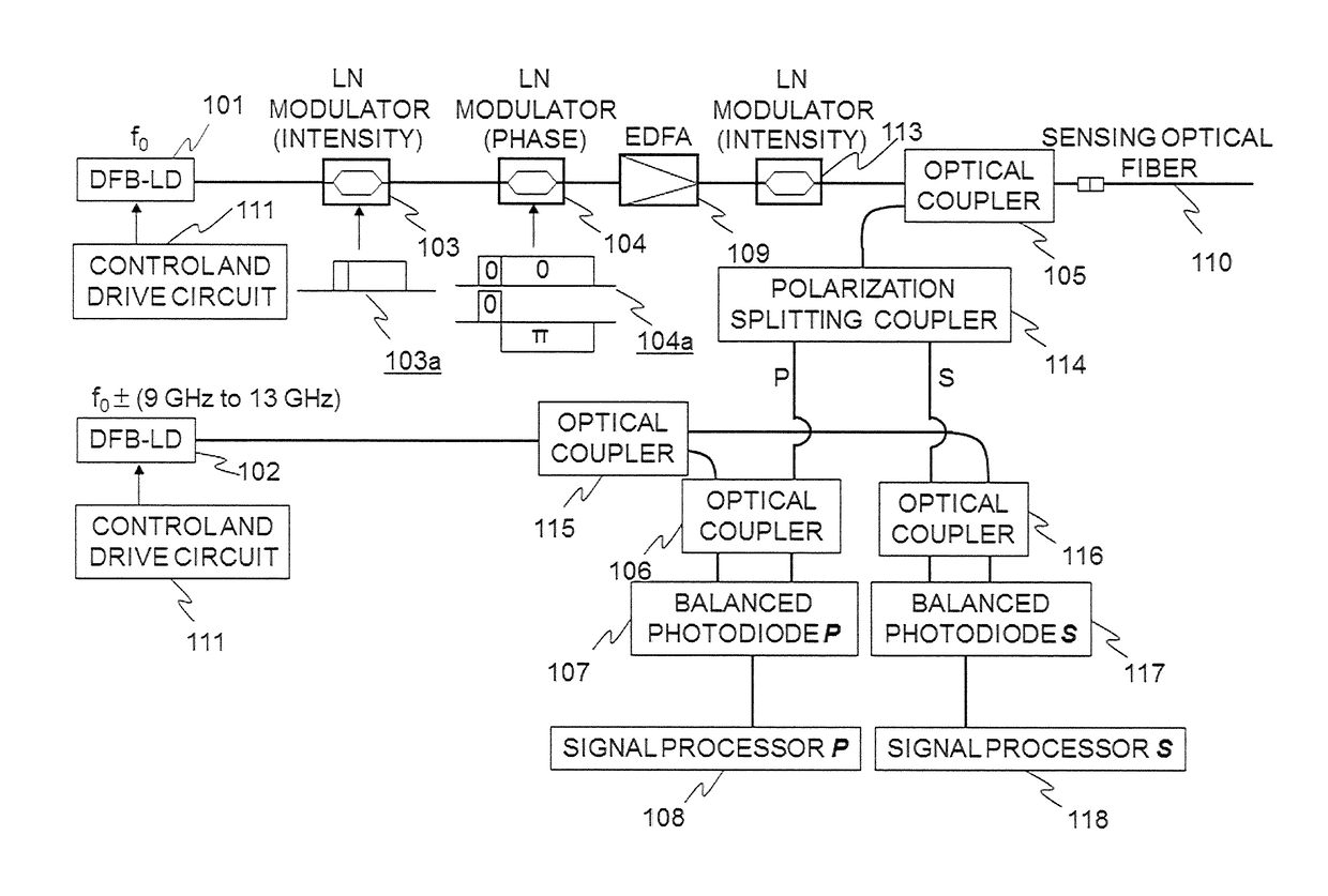
[0063]Another configuration of the Brillouin backscattered measurement system that implements the basic configuration and is different from the experimental setup shown in FIGS. 7A and 7B is described in detail with reference to FIG. 13. A laser light emitted from a distributed feedback laser diode (DFB-LD, oscillation frequency f0) 101 shown in upper portion of the figure is intensity-modulated to an optical pulse pair 103 by a first lithium niobate (LN) modulator 103, and then phase-modulated to two types of optical pulse pairs 104 by a second lithium niobate (LN) modulator 104 and amplified in power by an erbium-doped fiber amplifier (EDFA) 109. After that the amplified optical pulse pairs are entered into a third lithium niobate (LN) modulator 113 to be adjusted again in its intensity and then launched into a single-mode optical fiber (SMF), which is a sensing optical fiber, through an optical coupler 105. The backscattered lights produced in the optical fiber by the launched op...
PUM
 Abstract
Description
Claims
Application Information
 - R&D Engineer
- R&D Manager
- IP Professional
- Industry Leading Data Capabilities
- Powerful AI technology
- Patent DNA Extraction
Browse by: Latest US Patents, China's latest patents, Technical Efficacy Thesaurus, Application Domain, Technology Topic.
© 2024 PatSnap. All rights reserved.Legal|Privacy policy|Modern Slavery Act Transparency Statement|Sitemap