
Photovoltaic mounting system for solar tracker array

a technology of solar tracker array and mounting system, which is applied in the direction of photovoltaic supports, heat collector mounting/support, light and heating apparatus, etc., can solve the problems of cumbersome handling and pv modules, and achieve the effects of reducing costs, increasing installation speed, and connecting quickly and efficiently

Active Publication Date: 2017-08-31
TESLA INC
View PDF86 Cites 8 Cited by
  • Summary
  • Abstract
  • Description
  • Claims
  • Application Information

AI Technical Summary

Benefits of technology

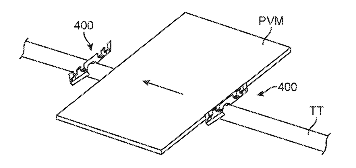
The invention provides better and faster ways to attach solar panels to a solar tracker. These brackets can be quickly and easily connected to the panels, and some of them allow a single installer to assemble a solar tracker without needing another person to hold the panels in place. This saves money and time during installation.

Problems solved by technology

PV modules are not often overly heavy, but instead very cumbersome to handle due to large surface areas.

Method used


Image

  • Photovoltaic mounting system for solar tracker array
  • Photovoltaic mounting system for solar tracker array
  • Photovoltaic mounting system for solar tracker array

Examples


Embodiment Construction

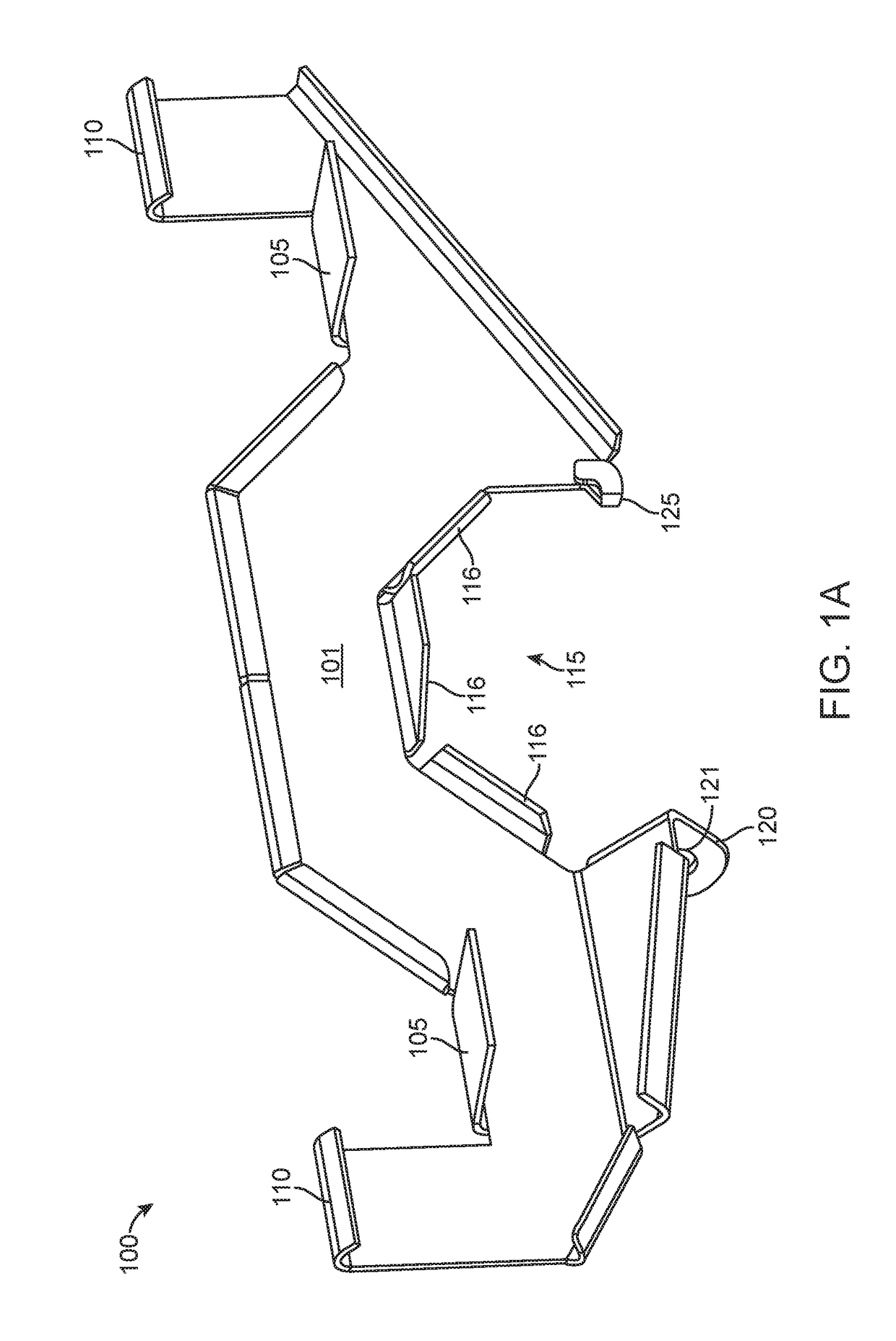
[0018]Referring now to the drawing figures, FIG. 1A illustrates a mounting system for a solar tracker according to various embodiments of the invention. The system can include bracket 100 that can include wall member 101, which can extend along a plane. Various features can extend from wall member 101, including for example, a plurality of ledge portions 105, plurality of attachment tabs 110, and collar portion 115. Such features can be formed from by cutting and bending shapes from wall member 101.

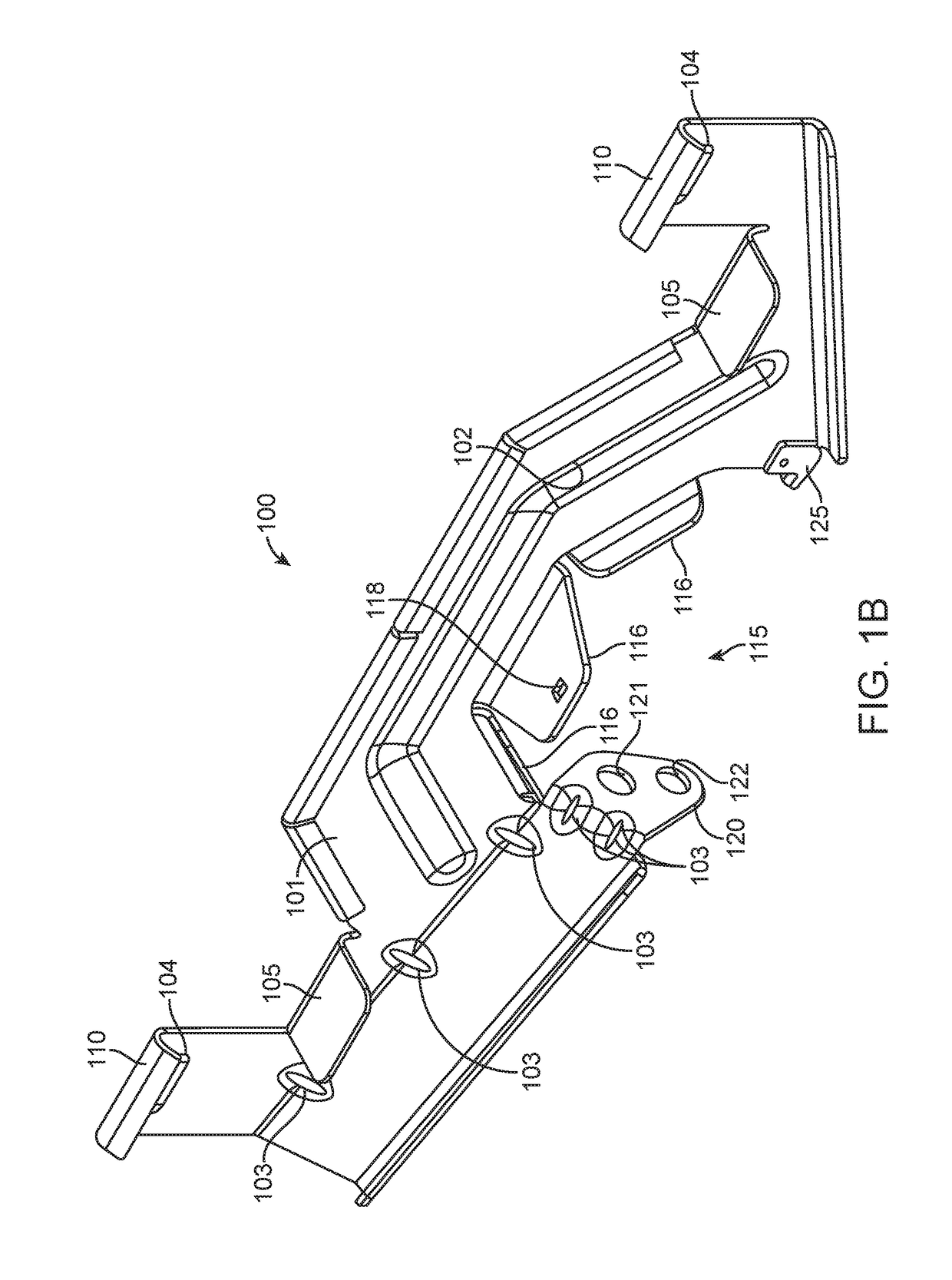
[0019]FIG. 1B shows an alternative arrangement of bracket 100, which shares many of the same features of the bracket shown at FIG. 1A, where wall member can include reinforcement portions 102. Reinforcement portions 102 can extend as ribs along wall member 101 and protrude outwardly or inwardly from a PV module that bracket 100 mounts to. Bumper portions 104 protrude outwardly from a PV module that bracket 100 mounts to. In this manner, bumper portions 104 can act as a spacer and bumper t...


PUM


Abstract

Mounting systems are disclosed for attaching photovoltaic modules to torque tubes. Such systems can include saddle brackets that maximize space along a torque tube by sharing torque tube mounting holes between adjacent brackets. The brackets can be positionally stable on the torque tube prior to complete installation to enable a single installer to assemble a complete tracker array.

Description

CROSS-REFERENCES TO RELATED APPLICATIONS[0001]This claims the benefit of U.S. Provisional Application No. 62 / 299,863, filed on Feb. 25, 2016, which is hereby incorporated by reference in its entirety.BACKGROUND OF THE INVENTION[0002]Solar trackers are used to rotate photovoltaic (PV) modules to keep them perpendicular to the direct rays of the sun. Keeping the array of PV modules at this orientation increases and ideally optimizes the amount of energy that can be generated by the array, because energy generated by a fixed tilt array drops off with the cosine of the angle of incidence of solar rays on the surface of each panel. Because tracker arrayscost more and have relatively low ground surface area utilization due to the required row-to-row spacing to prevent shading, trackers are typically used only in medium to large sized arrays (e.g., ≧1 megawatt). Although trackers add an additional cost per watt over fixed ground-mount systems, the cost is typically recouped on arrays of th...

Claims


Application Information

Patent Timeline
Patent Type & Authority Applications(United States)
IPC IPC(8): H02S20/32
CPCH02S20/32F24S25/632F24S25/634F24S30/425Y02E10/47Y02E10/50F24S25/12F24S25/63F24S25/65
Inventor HAAS, ROBERTMOLINA, DAVIDPESCE, KATHRYN AUSTINKARKHECK, JOHANN FRITZ
Owner TESLA INC
Learn More