Submerged Clarifier Launder

a clarifier and submerged technology, applied in the direction of sedimentation device making, sedimentation settling tank feeding/discharge, etc., can solve the problems of significant capital and operational costs, algae growth is a recurrent problem, and the installation of effluent settling algae sweeps, etc., to achieve the effect of reducing costs

Active Publication Date: 2017-09-07
OVIVO INC
View PDF8 Cites 11 Cited by
  • Summary
  • Abstract
  • Description
  • Claims
  • Application Information

AI Technical Summary

Benefits of technology

[0005]The present invention differs from previously known solutions to these problems by eliminating costs associated with effluent launders, weir plates and scum baffle plates, launder covers and/or algae sweeps. The current design req

Problems solved by technology

Algae growth is a recurrent problem in conventional clarifier effluent launders.
Sometimes effluent launder algae sweeps have been

Method used


Image

  • Submerged Clarifier Launder
  • Submerged Clarifier Launder
  • Submerged Clarifier Launder

Examples


Embodiment Construction

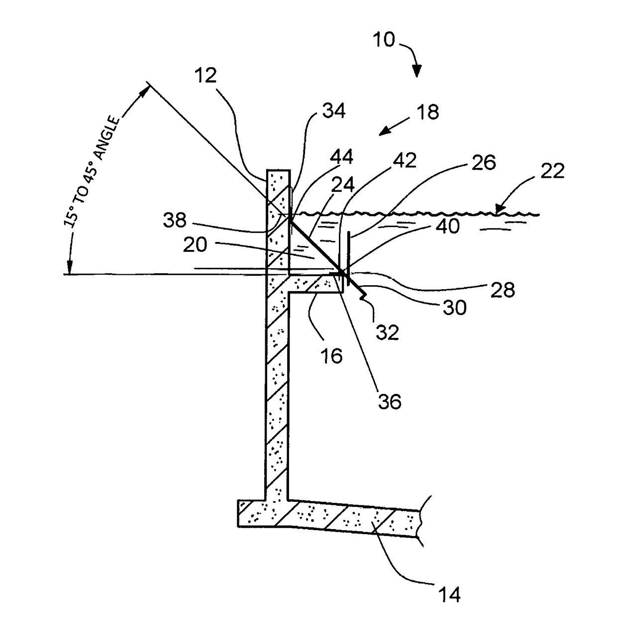
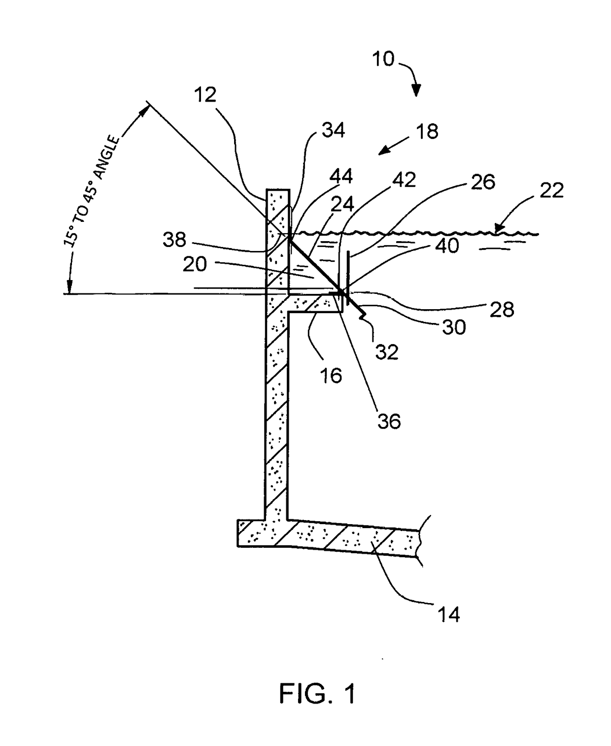
[0019]FIG. 1 shows an existing clarifier 10, typically of concrete but possibly of other material such as steel, in a partial cross section, including the outer wall 12 of the clarifier and a portion of the clarifier floor 14. The clarifier had an existing internal launder, but the vertical leg of the launder has been removed, leaving the horizontal shelf 16. This form of the invention replaces the conventional launder with a submerged effluent launder 18. The launder is formed as a hydraulic conduit 20 triangular in cross section as indicated in this schematic drawing. Liquid level of the clarifier is approximately at 22, and freely contacts the outside surface of an obliquely angled plate 24 forming the upper side of the new launder. A scum baffle 26 would be implemented as shown in the drawing, supported by intermittent baffle support brackets 28. In another implementation of the invention the liquid level can be lower.

[0020]The plate 24 preferably comprises an integral plate tha...


PUM

PropertyMeasurementUnit
Lengthaaaaaaaaaa
Densityaaaaaaaaaa
Levelaaaaaaaaaa

Abstract

A clarifier in a wastewater treatment plant is provided with a submerged launder for effluent, the launder preferably having an integral density current baffle and scum baffle. In one embodiment an existing launder is modified, with its vertical leg replaced with a sloped plate defining launder conduit triangular in cross section, and with a sloping portion of the plate forming a density current baffle. Openings in the sloped plate permit entry of effluent liquid, and the liquid level in a clarifier is controlled without an overflow weir plate. In another form submerged pipe with entry holes serves as the launder, with support brackets integral with a density current baffle. A third form of the launder is a box formed beneath the shelf of an existing internal launder in the clarifier, again with a density current baffle extending down from the box. In another version an existing launder is covered and sealed, and holes are drilled through the launder wall to admit effluent. A submerged launder avoids problems of algae buildup and the need for algae sweeps or frequent cleaning of the launder.

Description

BACKGROUND OF THE INVENTION[0001]This invention concerns wastewater treatment plants, particularly clarifiers, and is directed to an improved clarifier launder construction that eliminates algae buildup and the need for algae sweeps, launder covers or frequent cleaning.[0002]Clarifier launders typically are formed by a shelf of concrete, L-shaped in cross section and integral with the wall, on the inside or the outside of the clarifier wall. They can also be of other materials such as steel or FRP (fiberglass reinforced plastic). If inside, the conventional launder provides with its vertical leg a weir for overflow of effluent liquid into the launder with a weir plate attached to the top of the vertical leg. In an external concrete launder the top edge of the clarifier with weir plate attached provides the overflow weir.[0003]Algae growth is a recurrent problem in conventional clarifier effluent launders. The launders are exposed to daylight, promoting algae growth, and must be clea...

Claims


Application Information

Patent Timeline
IPC IPC(8): B01D21/00B01D21/24
CPCB01D21/0006B01D21/0003B01D21/2444B01D21/0042Y02W10/37
Inventor HEIMDAL, TORVORWALLER, JOHNCLARK, HUGH RYANKLINE, TODDPETRONE, RALPHHUGO, BRUCE A.PETERS, ROGERBEAMAN, TYSON
Owner OVIVO INC
Why Eureka
Try Eureka