Clamping system comprising a collar and individual pre-attachment clips

a technology of pre-attachment clips and clamping systems, which is applied in the direction of flanged joints, sleeve/socket joints, rod connections, etc., can solve the problems of affecting the surface of the parts in question, their geometrical shapes are relatively complex,

Active Publication Date: 2017-09-07
ESTAB CAILLAU SARL
View PDF0 Cites 21 Cited by
  • Summary
  • Abstract
  • Description
  • Claims
  • Application Information

AI Technical Summary

Benefits of technology

[0042]It is indicated above that it is possible to perform pre-attachment to the second tube by means of a washer, e.g. a washer that also has a sealing function. It is also possible to achieve the pre-attachment to the second tube by using individual clips that are analogous to the clips that are described in the present specification, and that are placed on the second flank of the collar.

Problems solved by technology

In addition, their geometrical shapes are relatively complex so as to enable them not only to be held correctly relative to the band of the collar over their entire peripheries, but also to retain the ends of the respective tubes with which they co-operate correctly relative to the collar.
Thus, the pre-attachment means that U.S. Pat. No. 7,770,937 proposes are relatively voluminous on the outside of the collar and suffer from the drawback of requiring a welding operation either on the outside periphery of the collar, or on one of the tubes.
Welding is an operation that is very distinct from the other operations required for manufacturing the collar or for assembling it with the tubes, and can damage the surface of the parts in question.

Method used


Image

  • Clamping system comprising a collar and individual pre-attachment clips
  • Clamping system comprising a collar and individual pre-attachment clips
  • Clamping system comprising a collar and individual pre-attachment clips

Examples


Embodiment Construction

[0064]The collar of the clamping system of the present specification is, for example, generally analogous to the one that is described in Documents EP 1 451 498 and EP 2 598 785.

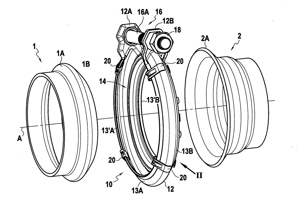
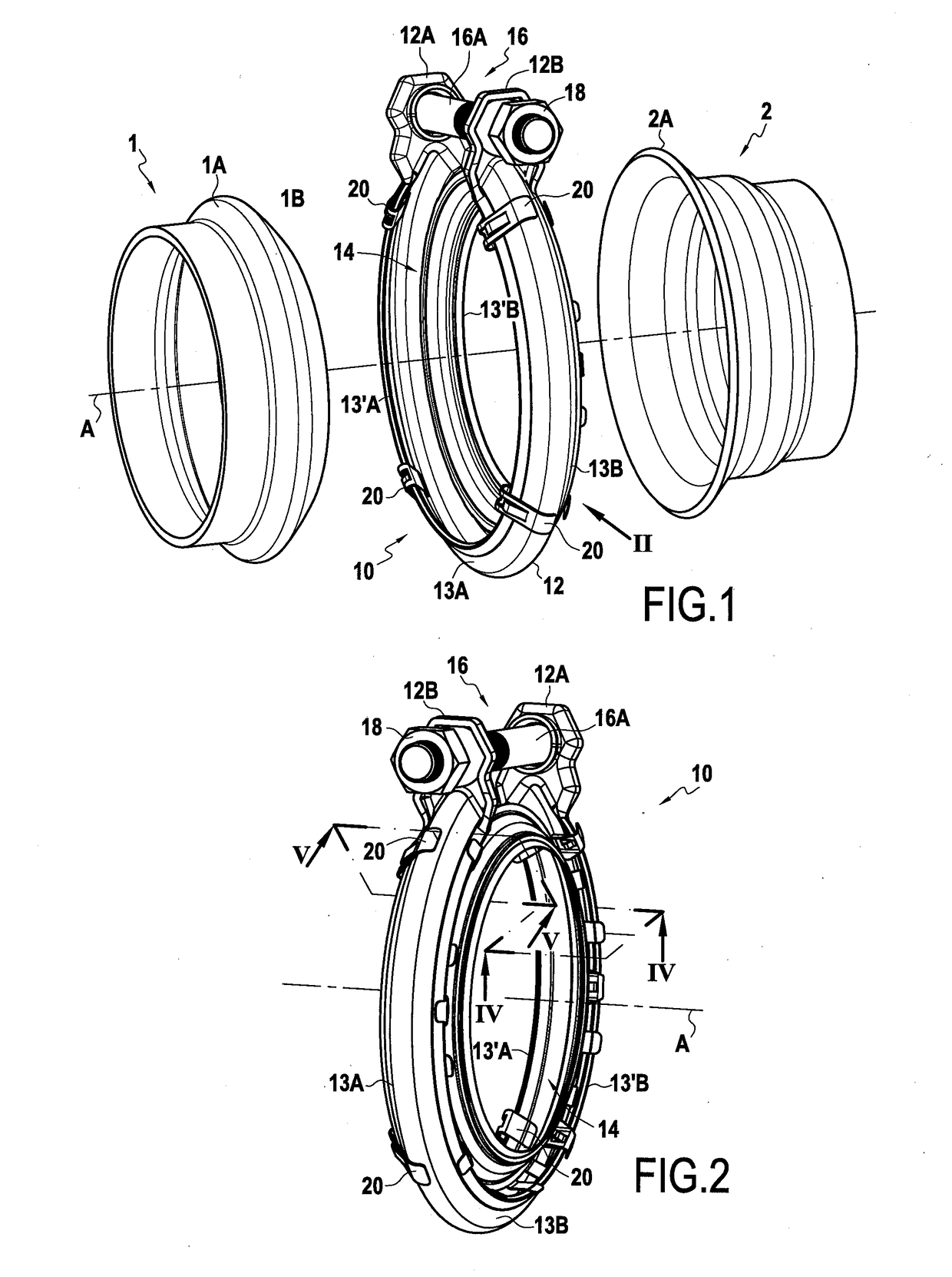
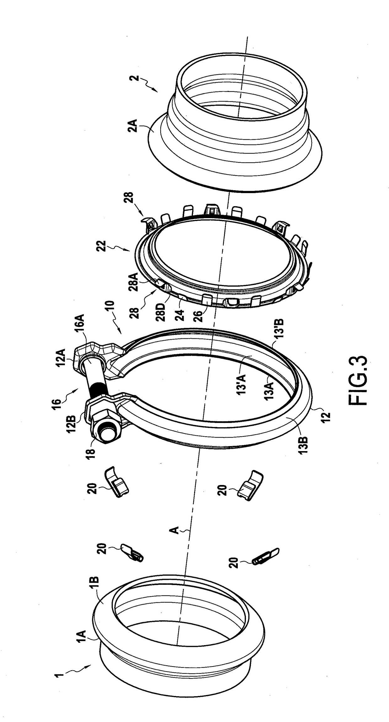
[0065]Thus, as can be seen, in particular, in FIGS. 1 to 3, said collar 10 has a band 12 that has a first flank 13A and a second flank 13B between which an inside trough 14 is defined.

[0066]Throughout the description below, and unless otherwise indicated, the term “inside” is used to describe elements that face towards the axis A of the collar or that are closer to that axis A relative to other elements that are said to be “outside”, “outside” elements also being those that face away from the axis A.

[0067]The clamping system serves to connect two tubes together via their ends. Thus, FIG. 1 shows a first tube 1 and a second tube 2 respectively having a first clamping surface 1A and a second clamping surface 2A that project relative to their respective cylindrical outside surfaces. For assembling together the ...


PUM


Abstract

The clamping system comprises a collar (10) having a band (12) that has two flanks (13A, 13B), between which an inside trough (14) is defined that receives projecting clamping surfaces (1A, 2A) of two tubes (1, 2) to be assembled together. The system further comprises a plurality of individual retaining clips (20) distributed angularly around the first flank (13A), each clip having an inside branch (30) and an outside branch (32) facing each other, and between which the first flank is pinched, and a retaining portion (34) that, in the pre-attached state, is suitable for co-operating with the clamping surface (1A) of the first tube (1), one of the branches carrying a first bearing zone (36) that co-operates with a first bearing surface (13′A) of the collar that faces towards the axis (A) of said collar.

Description

CLAIM OF PRIORITY[0001]This application claims priority from French Patent Application No. FR1651881, filed on Mar. 7, 2016 and is incorporated herein by reference in its entirety.BACKGROUND OF THE DISCLOSURE[0002]The present disclosure relates to a clamping system for connecting two tubes together in sealed manner, the facing ends of the two tubes having clamping surfaces that project relative to the cylindrical outside surfaces of said tubes, the system comprising a collar having a band suitable for co-operating with said clamping surfaces and means for tightening said band, the band having a first flank and a second flank between which an inside trough is defined that is suitable for receiving the clamping surfaces.[0003]A clamping system of this type is known from European Patent No. EP 1 451 498. The cross-section of the band of the collar is, for example, substantially V-shaped or U-shaped, so that the branches formed by the cross-sectional shape bear respectively against the ...

Claims


Application Information

Patent Timeline
Patent Type & Authority Applications(United States)
IPC IPC(8): F16L23/08
CPCF16L23/08F16L21/065F16L21/08F16L23/003F16L23/04F16B7/0406F16B2/065F16B2/20F16L21/00
Inventor VOSGEOIS, CYRILPREVOT, FABRICERIGOLLET, NICOLASGOULET, PATRICK
Owner ESTAB CAILLAU SARL
Why Eureka
Try Eureka