Air distribution duct in the passenger compartment of a motor vehicle

Inactive Publication Date: 2013-08-20
RENAULT SA
View PDF17 Cites 3 Cited by
  • Summary
  • Abstract
  • Description
  • Claims
  • Application Information

AI Technical Summary

Benefits of technology

[0009]Since the extruded duct is situated inside the crossmember, the space requirement for the distribution device is reduced. Moreover, producing the duct by extrusion makes it possible to reduce the quantities of material to be used, and hence the production cost. The rigidity of the extruded duct also enables it

Problems solved by technology

Moreover, producing the duct by extrusion makes it possible to reduce

Method used


Image

  • Air distribution duct in the passenger compartment of a motor vehicle
  • Air distribution duct in the passenger compartment of a motor vehicle
  • Air distribution duct in the passenger compartment of a motor vehicle

Examples


Embodiment Construction

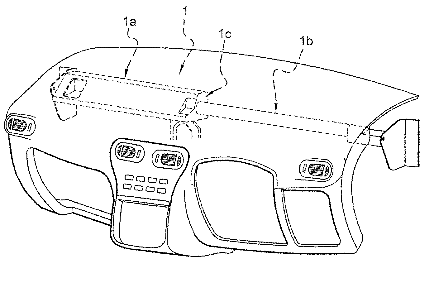
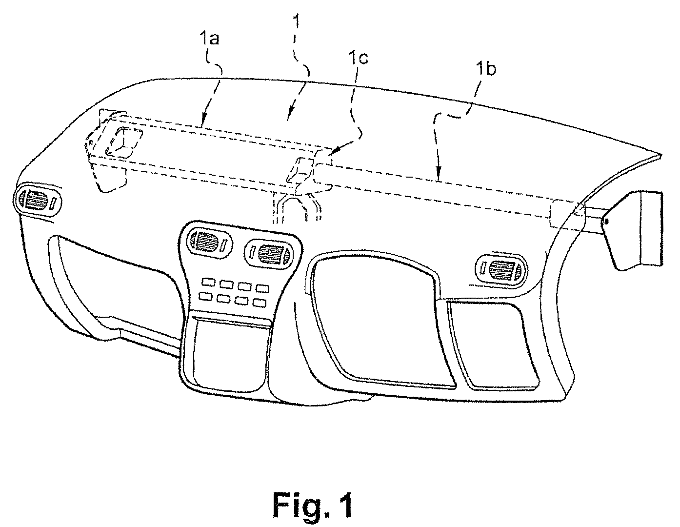
[0024]FIG. 1 represents a crossmember 1 for reinforcing the structure of the vehicle. This crossmember 1 is integrated inside the dashboard of the vehicle and supports structural elements such as the speedometer or the air-conditioning unit.

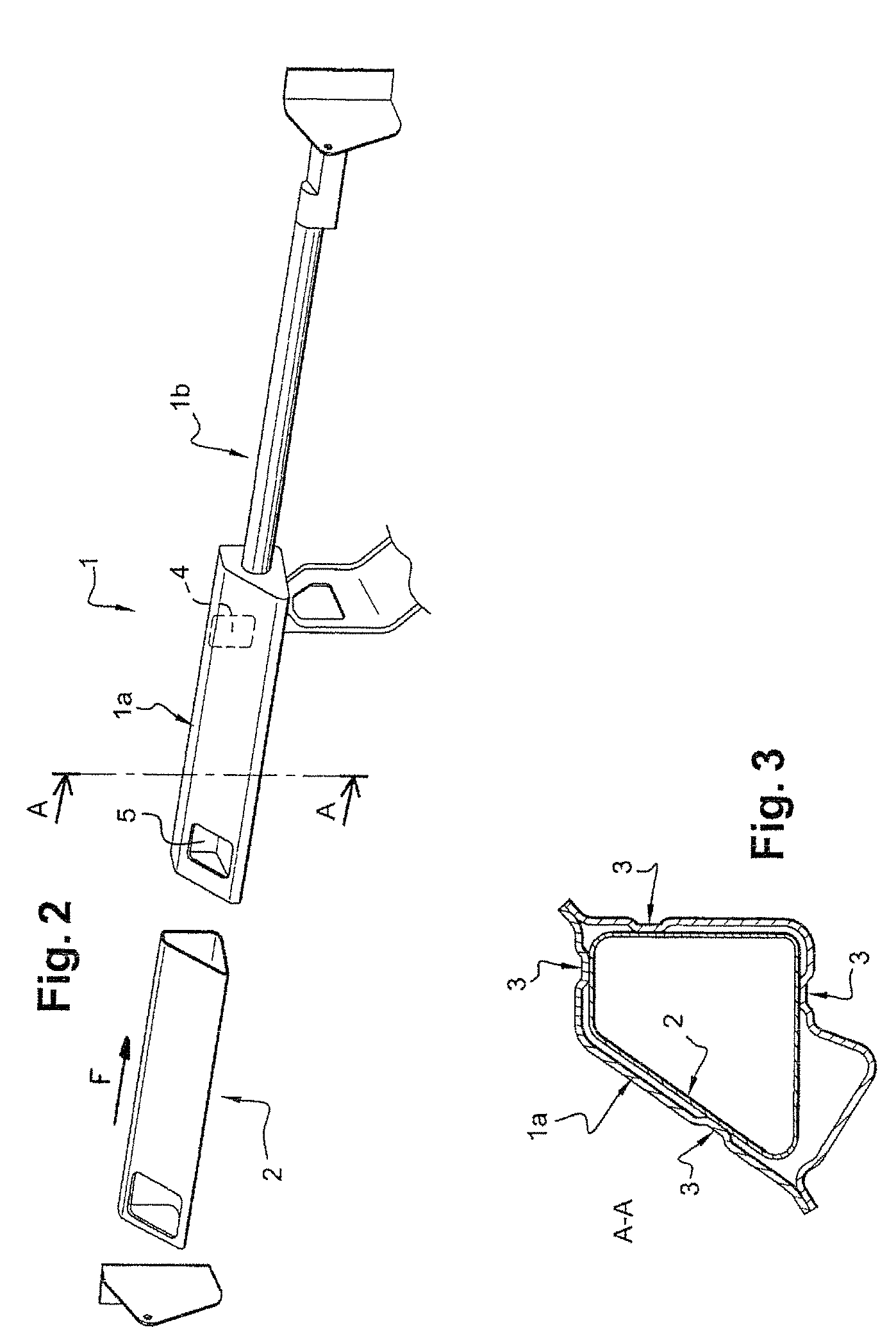
[0025]This crossmember 1 is, for example, situated near the lower edge of the windshield, inside the dashboard. It has a hollow closed cross section (FIG. 3) and is made of a rigid material, generally metal.

[0026]The distribution duct 2 is made of plastic and produced by extrusion. It is substantially parallelepipedal in shape and has two openings 4 and 5 placed one on each side of the duct. The first opening 4 is intended to receive the air coming from the air-conditioning unit so as to pass it, via the duct 2, toward the second opening 5. The latter is placed in communication with the vehicle cabin in a conventional manner so that the air, optionally heated or cooled, can be fed into said cabin.

[0027]As represented in FIG. 2, the air distributi...


PUM


Abstract

The invention relates to an air distribution duct (2) integrated in the passenger compartment of a motor vehicle comprising at least one rigid hollow crossmember (1) that reinforces the structure of the vehicle, characterized in that the duct (2) is made by extrusion and is placed in the crossmember (1) at a distance from the inside wall of the crossmember.

Description

BACKGROUND[0001]The present invention relates to an air distribution duct for distributing air into the cabin of a motor vehicle, and particularly relates to such a device connected to an air-conditioning unit which allows the air, optionally heated or cooled, to be fed in at various locations of the cabin.[0002]With the increased reduction in the noise nuisance produced by the vehicle engine, the air-conditioning unit has become a significant noise source to which the air distribution device contributes. Owing to the transmissivity of the air ducts of said device, the noise of the fan is propagated right into the cabin. Moreover, these ducts are themselves a source of noise resulting from the flow turbulence generated by their architecture.[0003]The known air distribution devices, generally arranged in the dashboard of the vehicle, also have the disadvantage of occupying a considerable amount of space, this space being complicated to manage at the vehicle design stage.[0004]One sol...

Claims


Application Information

Patent Timeline
IPC IPC(8): B60H1/00B60K37/00
CPCB60H1/0055B60H1/00564B62D25/142B62D65/02B60H1/242B60K37/04B62D25/081B62D25/145
Inventor BILLARD, XAVIERCOIFFIER, JEREMIE
Owner RENAULT SA
Why Eureka
Try Eureka