Claw pole type motor and pump

a technology of a claw pole and a pump, which is applied in the direction of machines/engines, mechanical equipment, and magnetic circuit shapes/forms/construction, etc., can solve problems such as function deterioration, and achieve the effects of reducing the quantity of materials used, saving material costs, and suppressing the function of the iron cor

Inactive Publication Date: 2009-03-26
MATSUSHITA ELECTRIC WORKS LTD
View PDF7 Cites 4 Cited by
  • Summary
  • Abstract
  • Description
  • Claims
  • Application Information

AI Technical Summary

Benefits of technology

[0012]In accordance with a first aspect of the present invention, the cutout portions is provided in the iron core so that it makes possible to reduce the quantity of the material used in forming the iron core, thereby saving material cost and the like. Since the cutout portions are formed in the non-magnetic path regions of the iron core, there is no possibility that the cutout portions act as an obstacle in the magnetic path. This makes it possible to suppress deterioration of the function of the iron core as the magnetic circuit.
[0013]In accordance with a second aspect of the present invention, the cutout portions help to widen the cavity portions of the iron core. Therefore, in case of molding the stator in a pump, it is possible to widen the flow path of a molding material in the iron core. This enhances moldability, which leads to an increase in the yield and a decrease in the production cost.

Problems solved by technology

Although the material cost can be saved by removing unnecessary portions, it would be undesirable if this results in deterioration of the function of the iron core as the magnetic circuit.

Method used


Image

  • Claw pole type motor and pump
  • Claw pole type motor and pump
  • Claw pole type motor and pump

Examples


first embodiment

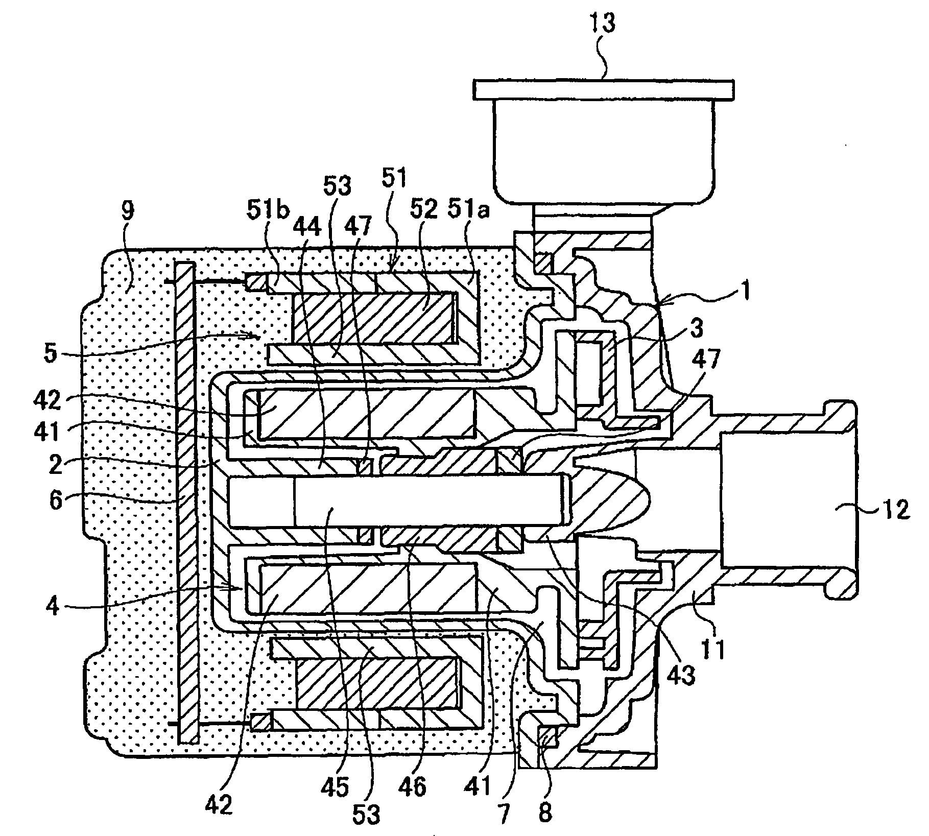
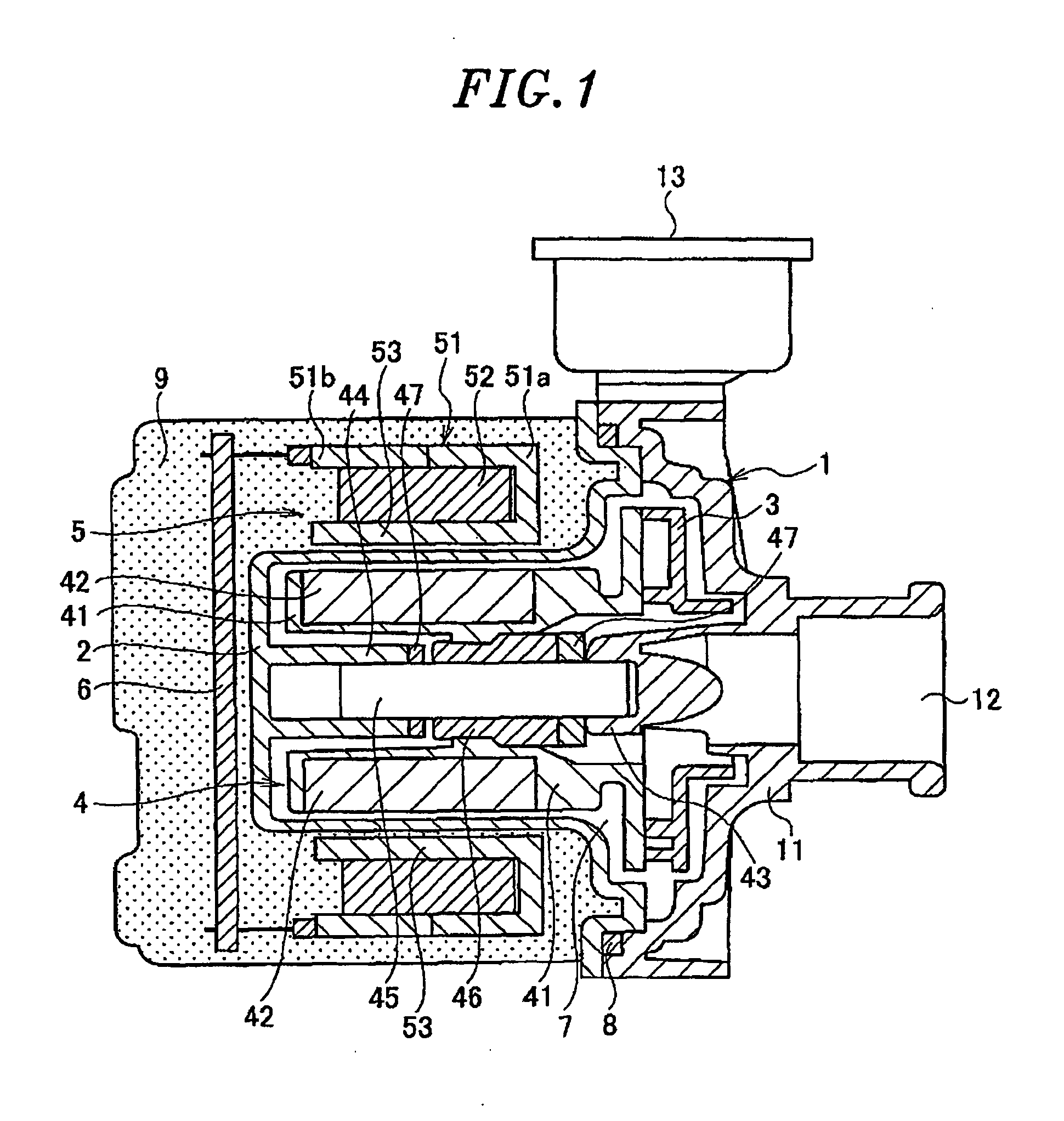
[0025]FIG. 1 is a section view showing a pump in accordance with a first embodiment of the present invention. This pump makes use of a claw pole type motor as its driving power source and is mainly formed of a pump case 1, a partition 2, an impeller 3, a rotor 4, a stator 5 and a control circuit board 6.

[0026]The pump case 1 and the partition 2 are coupled together to define a pump chamber 7. A seal member 8 is arranged in the coupling portion of the pump case 1 and the partition 2 to secure liquid-tightness of the pump chamber 7. The impeller 3 and the rotor 4 are rotatably received within the pump chamber 7 in a mutually integrated state. The stator 5 is arranged around the rotor 4 in a facing relationship with the latter, with the partition 2 interposed therebetween, thereby forming a so-called inner rotor structure. The entire portions of the pump except the pump case 1 are covered with a molded resin 9. In other words, the partition 2, the stator 5 and the control circuit board...

second embodiment

[0044]FIGS. 6A and 6B are schematic perspective views of the stator 5 in accordance with a second embodiment of the present invention, which correspond to FIGS. 3A and 3B showing the first embodiment. The pump of the second embodiment differs from that of the first embodiment in terms of the structure of the stator 5. The same parts as in the first embodiment will be designated by like reference numerals and will be omitted from duplicate description. Hereinafter, description will proceed with emphasis placed on the different points.

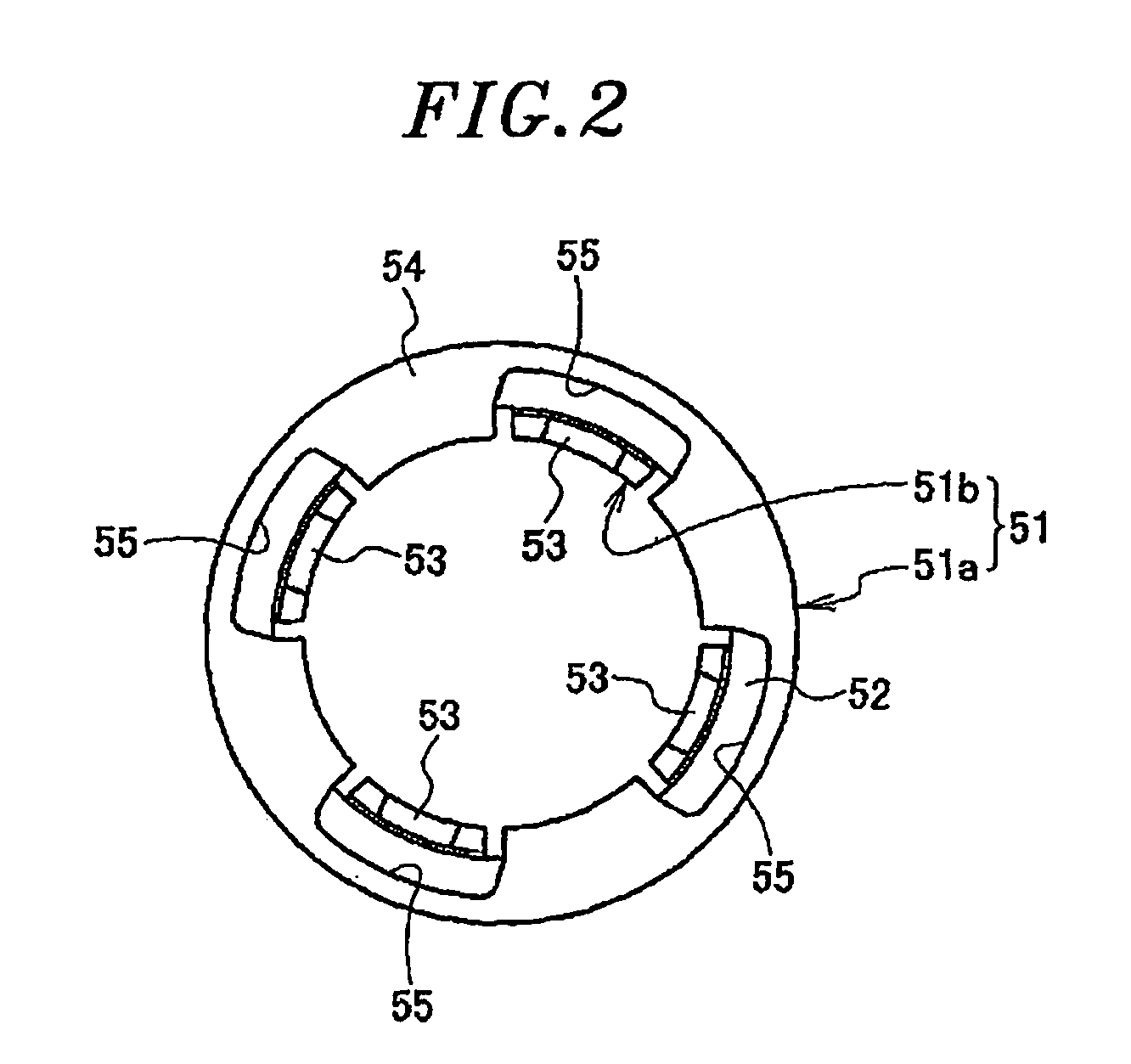
[0045]As in the first embodiment, the stator 5 includes an annular iron core 51 and an annular coil 52 received within the iron core51. The iron core 51 includes a yoke portion and a plurality of claw-shaped magnetic poles 53. The yoke portion has a generally C-like cross sectional shape opened in the inner circumferential surface opposite to the rotor 4. The yoke portion has a cylindrical sidewall portion 56 for covering the outer circumferential surfac...


PUM


Abstract

A claw pole type motor includes a rotor having a magnet arranged on an outer circumferential surface thereof and a stator including an annular iron core and an annular coil received within the iron core. The iron core includes a yoke portion opened in an inner circumferential surface opposite to the rotor, a plurality of upper claw-shaped magnetic poles and a plurality of lower claw-shaped magnetic poles which are arranged along an inner circumferential surface of the annular coil. The upper/lower claw-shaped magnetic poles are curved to extend axially downwardly/upwardly from an upper/lower inner edge of the yoke portion, respectively. The upper and the low claw-shaped magnetic poles are alternately arranged along a circumferential direction of the iron core. The yoke portion has cutout portions formed in non-magnetic path regions which do not include magnetic paths through which magnetic flux flows between neighboring claw-shaped magnetic poles across the annular coil.

Description

FIELD OF THE INVENTION[0001]The present invention relates to a claw pole type motor and a pump using the motor as a driving power source.BACKGROUND OF THE INVENTION[0002]It is known that a pump for sucking and discharging, e.g., liquid, employs a claw pole type motor with claw-shaped magnetic poles as a motor for rotatingly driving an impeller (see, e.g., Japanese Patent Laid-open Application No. 2003-505648). The claw pole type motor is simple in structure and therefore is advantageous in that it can enjoy enhanced productivity and reduced production costs thereof.[0003]A stator of a claw pole type motor is formed of an iron core having a plurality of claw-shaped magnetic poles arranged in a circumferential direction and an annular coil received within the iron core. The iron core serves as a magnetic circuit and is formed of a molded article. Although the material cost can be saved by removing unnecessary portions, it would be undesirable if this results in deterioration of the fu...

Claims


Application Information

Patent Timeline
Patent Type & Authority Applications(United States)
IPC IPC(8): H02K1/12H02K7/14
CPCH02K1/145H02K5/128H02K7/14H02K2211/03H02K15/12H02K21/145H02K11/0073H02K11/33F04D13/06
Inventor HASHIMOTO, TOSHIHARUINOUE, HIROKIYABUUCHI, HIDEKAZUNISHIKATA, MASAAKISUEMATSU, SHINJI
Owner MATSUSHITA ELECTRIC WORKS LTD
Why Eureka
Try Eureka