This helps you quickly interpret patents by identifying the three key elements:
Problems solved by technology
Method used
Benefits of technology
Benefits of technology
The patent text describes an electronic device that is designed to be waterproof, which helps to solve issues that were previously present with traditional electronic devices.
Problems solved by technology
However, when the controlling component is used after a period of time, a portion of the gasket (or the rubber ring) abutted against the controlling component easily generates a deformation problem, so water may flow into the waterproof space by passing through the deformed gasket.
Method used
Image
Click on the blue label to locate the original text in one second.
Reading with bidirectional positioning of images and text.
Examples
first embodiment
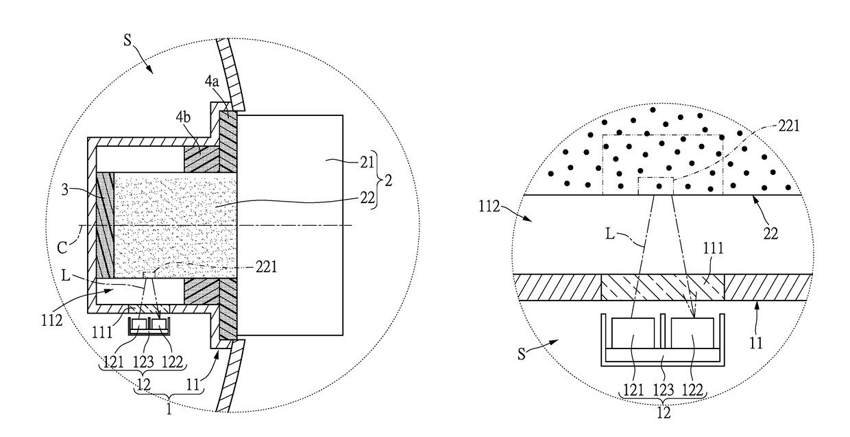
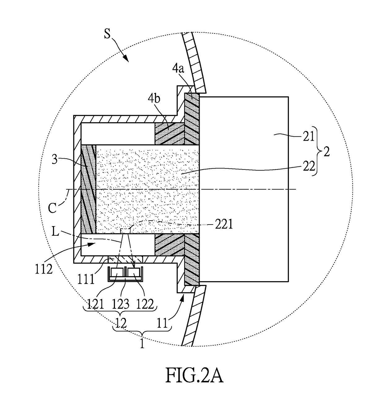
[0022]Please refer to FIGS. 1 through 4B, which show a first embodiment of the instant disclosure. References are hereunder made to the detailed descriptions and appended drawings in connection with the instant invention. However, the appended drawings are merely shown for exemplary purposes, rather than being used to restrict the scope of the instant invention.
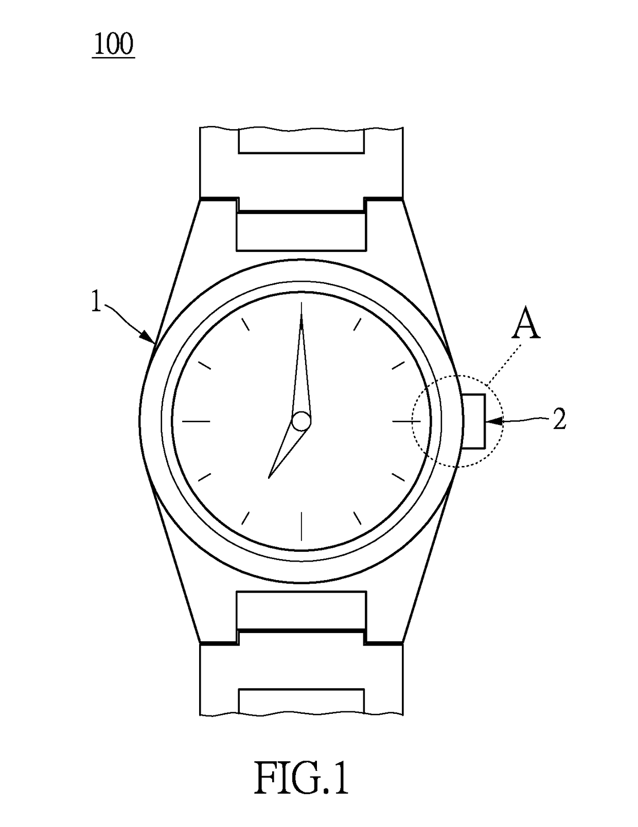
[0023]Please refer to FIGS. 1 and 2A, which show an electronic device 100 (e.g., watch, glasses, earphone, and so on) with a waterproof structure, but the electronic device 100 is not limited to the instant embodiment. In other words, the electronic device 100 in the instant disclosure may be a non-wearable device (not shown, such as cellphone or mouse). In order to clearly disclose the instant disclosure, the electronic device 100 in the instant embodiment takes a wearable device 100 (i.e., watch) for an example.
[0024]The wearable device 100 includes an assembly 1, at least one manipulation member 2 (i.e., rod, knob, or butt...
second embodiment
[0041]Please refer to FIGS. 5 and 6, which show a second embodiment of the instant disclosure. The electronic device 100 (or the wearable device 100) of the second embodiment is similar to that of the first embodiment, so the same features of the two embodiments are not disclosed again. The different features of the two embodiments are disclosed as follows.
[0042]The manipulation member 2 has a light guiding path (not labeled), and the manipulation member 2 is configured to receive an external light L′ from outside of the wearable device 100, wherein the external light L′ is guided toward the sensor array 122 by traveling in the light guiding path and then passing through the translucent region 111.
[0043]For example, the manipulation member 2 is made of a light guiding material, and a light reflecting material is coated on an outer surface of the manipulation member 2, so the manipulation member 2 can be used to guide light and provides the light guiding path therein. A plurality of ...
PUM
Abstract
An electronic device with waterproof structure includes an assembly and a manipulation member movably disposed on an outer surface of the assembly. The assembly includes a case and an optical detection module. The case defines a waterproof space and has a translucent region. The optical detection module is arranged in the waterproof space. The optical detection module has a lighting unit and a sensor array. Light emitted from the lighting unit enables to travel out of the waterproof space by penetrating through the translucent region. At least part of the manipulation member is corresponding in position to the translucent region. The lighting unit is configured to emit light onto the manipulation member, and the sensor array is configured to receive the light reflected from the manipulation member.
Description
BACKGROUND OF THE INVENTION[0001]1. Field of the Invention[0002]The instant invention relates to a waterproof device; in particular, to an electronic device with waterproof structure.[0003]2. Description of Related Art[0004]The conventional electronic device (e.g., wearable device) includes a mechanical detection switch and a controlling component (e.g., knob or button) for triggering the mechanical detection switch. The conventional electronic device is provided with a waterproofed space by arranging a gasket or a rubber ring outside the mechanical detection switch and the controlling component, thereby making it waterproof. In other words, the mechanical detection switch and the controlling component must be arranged in the waterproof space.[0005]However, when the controlling component is used after a period of time, a portion of the gasket (or the rubber ring) abutted against the controlling component easily generates a deformation problem, so water may flow into the waterproof s...
Claims
Application Information
Patent Timeline
Application Date:The date an application was filed.
Publication Date:The date a patent or application was officially published.
First Publication Date:The earliest publication date of a patent with the same application number.
Issue Date:Publication date of the patent grant document.
PCT Entry Date:The Entry date of PCT National Phase.
Estimated Expiry Date:The statutory expiry date of a patent right according to the Patent Law, and it is the longest term of protection that the patent right can achieve without the termination of the patent right due to other reasons(Term extension factor has been taken into account ).
Invalid Date:Actual expiry date is based on effective date or publication date of legal transaction data of invalid patent.

