
Increasing returned light in a compact augmented reality / virtual reality display

a virtual reality display and compact technology, applied in the field of optical arrangement, can solve the problems of limited interaction outside the virtual world, image of the physical scene from different perspectives may not incorporate the user's alterations, and the interaction is typically limited

Active Publication Date: 2017-09-07
DISNEY ENTERPRISES INC
View PDF3 Cites 35 Cited by
  • Summary
  • Abstract
  • Description
  • Claims
  • Application Information

AI Technical Summary

Benefits of technology

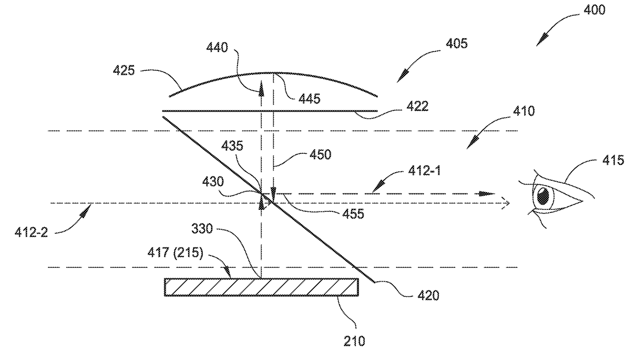
This patent describes an augmented reality display device that can show polarized light generated by a display with a specific polarization axis. The device has an optical arrangement that includes a mirror element, a polarized beam splitter element, a half-wave plate element, a quarter-wave plate element, and a polarized reflector. The optical arrangement has a predefined arrangement relative to the display and defines a field of view. The device can display different portions of the polarized light onto the field of view using the optical arrangement. The technical effect of this invention is to provide an improved augmented reality display device that can show more precise and accurate information in a more realistic way.

Problems solved by technology

However, such interactions are typically limited to the virtual world, and any interactions outside the virtual world are limited (e.g., a hand-held gaming device could vibrate when certain actions occur).
However, as such alterations apply only to a single image of the physical scene, subsequent captured images of the physical scene from different perspectives may not incorporate the user's alterations.

Method used


Image

  • Increasing returned light in a compact augmented reality / virtual reality display
  • Increasing returned light in a compact augmented reality / virtual reality display
  • Increasing returned light in a compact augmented reality / virtual reality display

Examples


Embodiment Construction

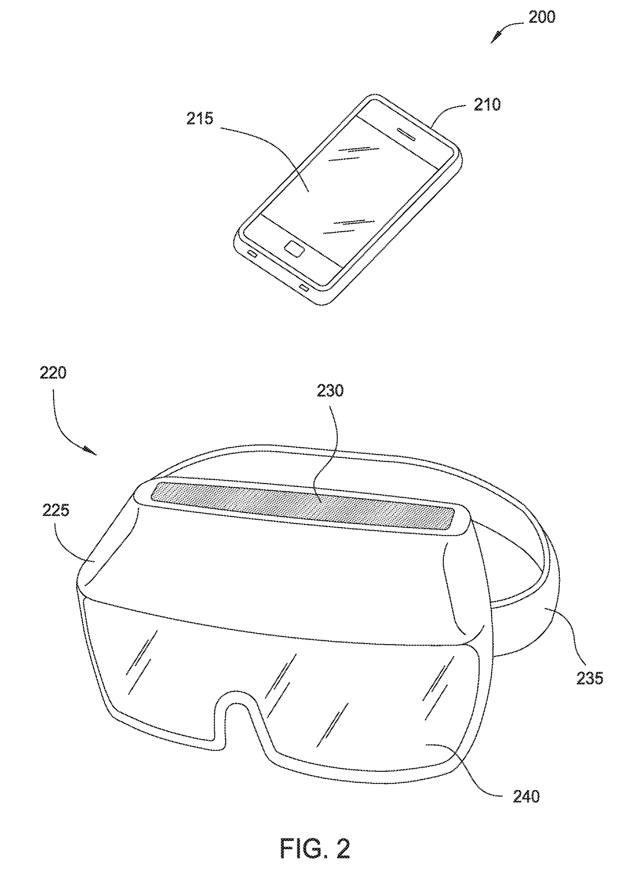
[0016]For implementations of an AR-capable and / or VR-capable display device including a display for displaying imagery, it is generally desirable to capture as much light emitted by the display as possible. In some implementations, such as those incorporating an external display device (such as a smartphone or other mobile computing device of a wearer), the display may be configured to produce polarized light. For the different types of polarization, it is possible to preserve a significant amount of polarized light emitted by the display by utilizing polarized beam splitter elements and / or polarized reflectors that maximize the amount of reflected and / or transmitted light at various stages.

[0017]Further, modularity and compatibility of the AR / VR-capable display device with various types of mobile computing devices are generally desirable features. However, since different models of smartphones can emit polarized light in different planes of polarization, an arrangement of a particu...


PUM


Abstract

Implementations of an augmented reality (AR)-capable display device for displaying polarized light generated by a display onto a predefined field of view are disclosed herein. The display device comprises an optical arrangement having a predefined arrangement relative to a predefined position of the display and defining the field of view. The optical arrangement comprises a mirror element disposed within the field of view and at least partially transmissive of ambient light incident on a first surface and at least partially reflective of light incident on an opposite second surface, a polarized beam splitter element disposed within the field of view and closer to the second surface of the mirror element than the first surface, a half-wave plate element disposed between the polarized beam splitter element and the display and outside the field of view, and a quarter-wave plate element disposed between the polarized beam splitter element and the mirror element.

Description

CROSS-REFERENCE TO RELATED APPLICATIONS[0001]This application claims benefit of U.S. provisional patent application Ser. No. 62 / 303,141, filed Mar. 3, 2016, entitled “INCREASING RETURNED LIGHT IN A COMPACT AUGMENTED REALITY / VIRTUAL REALITY DISPLAY”, which is herein incorporated by reference in its entirety.BACKGROUND[0002]Field of the Disclosure[0003]The present disclosure generally relates to computer-based entertainment, and more specifically to optical arrangements suitable for augmented reality (AR) and / or virtual reality (VR) devices.[0004]Description of the Related Art[0005]Computer graphics technology has significantly progressed since the first video games were developed. Relatively inexpensive 3D graphics engines now provide nearly photo-realistic interactive game play on hand-held video game, home video game, and personal computer hardware platforms costing only a few hundred dollars. These video game systems typically include a hand-held controller, game controller, or, i...

Claims


Application Information

Patent Timeline
IPC IPC(8): G02B27/01G06F1/16A63F13/25G02B27/28
CPCG02B27/0172G02B27/283G02B27/286G02B27/0176A63F2300/8082A63F13/25G02B2027/0156G02B2027/014G06F1/163
Inventor HASELTINE, ERIC C.
Owner DISNEY ENTERPRISES INC
Learn More