Spinal implant structure and kit thereof

a technology of spine and implant, applied in the field of spine implant structure, can solve the problems of destabilizing the spine, unsatisfactory prior art, mechanical damage to the spine, etc., and achieve the effect of efficient and easy operation

Active Publication Date: 2017-09-14
WILTROM
View PDF25 Cites 16 Cited by
  • Summary
  • Abstract
  • Description
  • Claims
  • Application Information

AI Technical Summary

Benefits of technology

[0007]The present invention provides a spinal implant structure kit, comprising a spinal implant structure and an operating tool for use with the spinal implant structure. The spinal implant structure structurally matches the operating tool so that vertebroplasty can be performed efficiently and easily in terms of the adjustment of the position of the spinal implant structure, expansion of the vertebral body, and perfusion of a bone cement, etc.

Problems solved by technology

Severe osteoporosis, intervertebral disc degeneration, ligament degeneration, joint dislocation, and joint compression may bring mechanical damage to the spine (such as a spinal compression fracture) and thus destabilize the spine.
Spinal instability is accompanied by extreme discomfort and pain, thereby predisposing the patient to chronic back pain, spine curvature disorders, and walking disability.
However, the prior art is unsatisfactory and thus still has room for improvement.

Method used


Image

  • Spinal implant structure and kit thereof
  • Spinal implant structure and kit thereof
  • Spinal implant structure and kit thereof

Examples


first embodiment

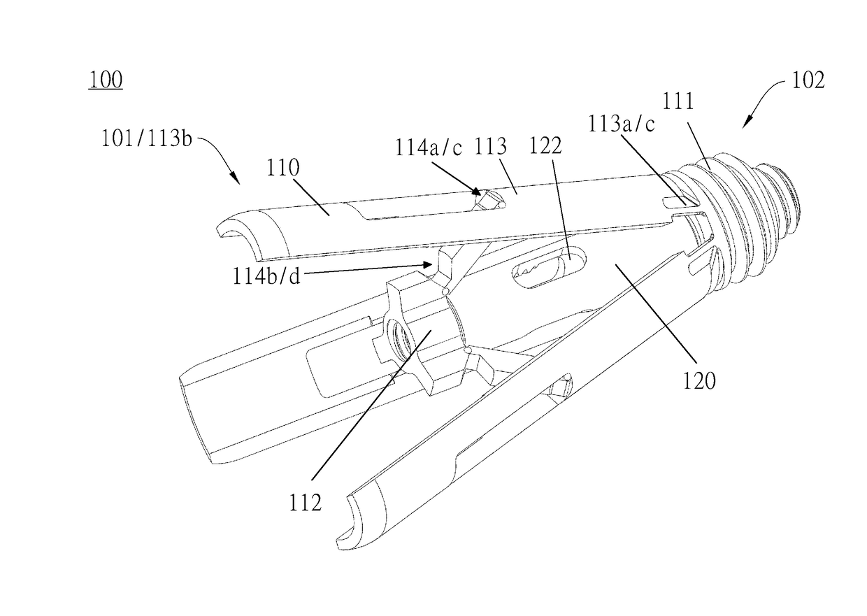
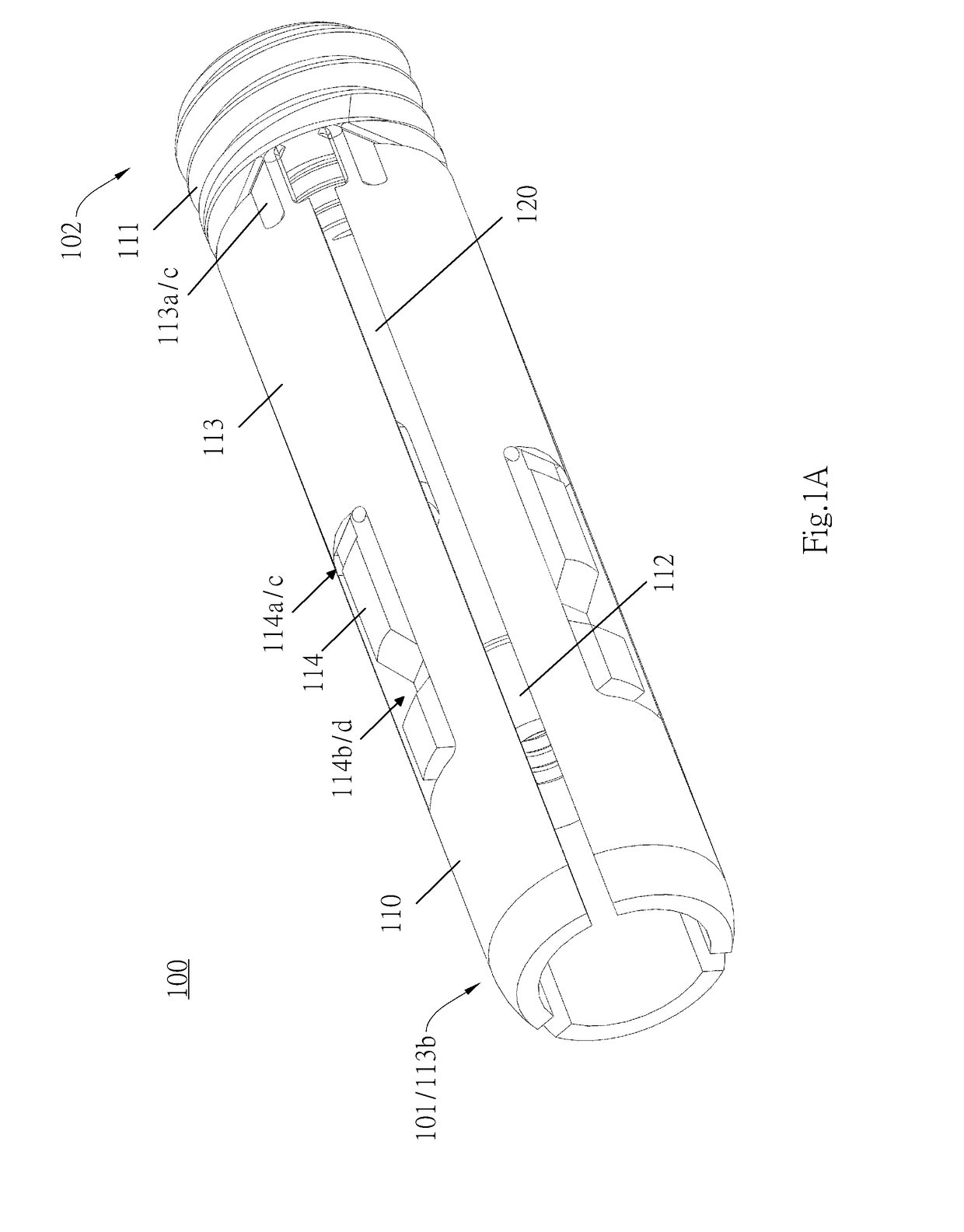
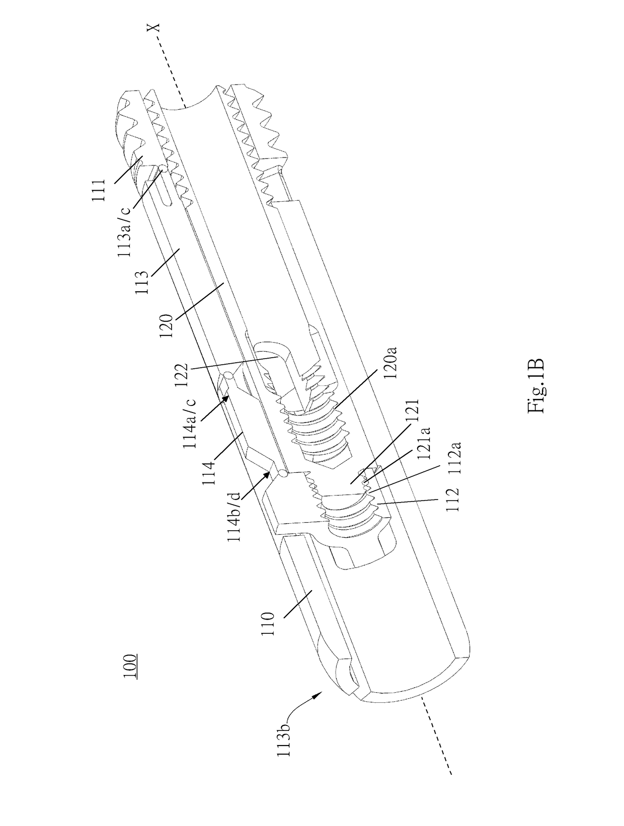
[0022]The spinal implant structure 100, which is not netted, is illustrated by FIG. 1A through FIG. 2C. Referring to FIG. 1A and FIG. 1B, there are shown a lateral view and a cross-sectional view of the spinal implant structure 100 which is folded, respectively. FIG. 2A through FIG. 2C are a lateral view, a cross-sectional view, and a front view of the spinal implant structure 100 which has been expanded, respectively. Referring to FIGS. 1A, 1B, 2A, 2B, the spinal implant structure 100 comprises a body 110 and a fixing screw barrel 120. When the spinal implant structure 100 is folded, the body 110 becomes a hollow-cored cylinder, and the fixing screw barrel 120 also becomes a hollow-cored cylinder. The spinal implant structure 100 has an expansion end 101 (left end) and a fixing end 102 (right end). The expansion end 101 is expanded with the operating tool (referring to FIG. 1A and FIG. 2A), and the degree of expansion can be adjusted as needed.

[Body]

[0023]The body 110 of the spinal...

second embodiment

[0034]FIG. 5A through FIG. 6C show that the spinal implant structure 200 is not netted. The spinal implant structure 200 of the second embodiment is identical to the spinal implant structure 100 of the first embodiment in terms of most technical features. For the sake of brevity, the identical technical features are not described herein.

[0035]FIG. 5A and FIG. 5B are a lateral view and a cross-sectional view of the spinal implant structure 200 which is folded, respectively. FIG. 6A through FIG. 6C are a lateral view, a cross-sectional view, and a front view of the spinal implant structure 200 which has been expanded, respectively. Referring to FIGS. 5A, 5B, 6A, 6B, the spinal implant structure 200 comprises a body 210 and a fixing screw barrel 220. When the spinal implant structure 200 is folded, the body 210 is a hollow-cored cylinder, and the fixing screw barrel 220 is also a hollow-cored cylinder. The spinal implant structure 200 has an expansion end 201 (left end) and a fixing en...


PUM


Abstract

The present invention provides a spinal implant structure. The spinal implant structure comprises a first part, a second part and at least one expansion arm. The second part is disposed on the horizontal orientation of the first part and does not overlap with the first part. The diameter of the first part is larger than that of the second part. One end of the expansion arm is connected to the first part, and the other end of the expansion arm is free end. The expansion arm and the first part create an angle. The expansion arm includes a supporting arm. One end of the supporting arm is connected to the expansion arm, and the other end of the supporting arm is connected the second part. The support arm includes a plurality of structure weakness. When the distance between the first part and the second part changes, the support arm bends from the structure weakness, thereby the angle is increased and the spinal implant structure is expanded. The first part, the second part, the expansion arm and the supporting arm are integrally formed.

Description

BACKGROUND OF THE INVENTION[0001]Field of the Invention[0002]The present invention relates to spinal implant structures and, more particularly, to an intervertebral and intravertebral implant and a tool kit thereof.[0003]Description of the Prior Art[0004]The spine, also known as the vertebral column, essentially comprises four types of elements, namely the spinal cord, vertebrae, ligaments, and intervertebral discs. Severe osteoporosis, intervertebral disc degeneration, ligament degeneration, joint dislocation, and joint compression may bring mechanical damage to the spine (such as a spinal compression fracture) and thus destabilize the spine. Spinal instability is accompanied by extreme discomfort and pain, thereby predisposing the patient to chronic back pain, spine curvature disorders, and walking disability.[0005]Among the ways to cure spinal instability is vertebroplasty, which entails placing an implant in a collapsed vertebral body. The implant in the collapsed vertebral body...

Claims


Application Information

Patent Timeline
Patent Type & Authority Applications(United States)
IPC IPC(8): A61F2/44A61F2/46
CPCA61F2/446A61F2/4611A61F2002/4475A61F2002/4495A61F2002/30405A61B17/7071A61B17/7074A61B17/8805A61B17/7094A61B17/7097A61B17/8858A61B17/8852A61F2002/30593
Inventor TSENG, CHANG-HOTSAI, MENG-YUAN
Owner WILTROM
Why Eureka
Try Eureka