Dual clutch

Active Publication Date: 2017-09-14
SCHAEFFLER TECH AG & CO KG
View PDF7 Cites 0 Cited by
  • Summary
  • Abstract
  • Description
  • Claims
  • Application Information

AI Technical Summary

Benefits of technology

This patent describes a dual clutch device for vehicles that can be used in a compact design, reducing production costs. The device includes a leaf spring element that amplifies compression based on distortion, reducing the actuating force for clutches and allowing for a simplified actuating system. The use of radially offset flat spring-clutches can also save axial structural space, making the device narrower and suitable for a larger angle of the motorcycle's installation. The friction clutches are arranged on different radial sides of a common element, further reducing the number of components required. The device can be implemented for running in an oil bath for cooling, lubrication, or cleaning purposes, and can be easily integrated with a transmission. Overall, this patent provides a compact, cost-effective, and efficient solution for dual clutch devices in vehicles.

Problems solved by technology

If the torque to be transferred is strong, the rider can be overwhelmed over an extended period of time.
Power clutches may however require a relatively large structural space and are associated with certain complexity.
Such a complex dual clutch can lead to increased costs for development and production.

Method used


Image

  • Dual clutch
  • Dual clutch
  • Dual clutch

Examples


Embodiment Construction

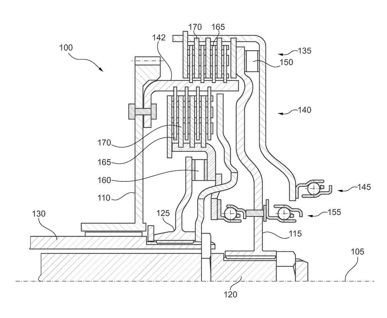
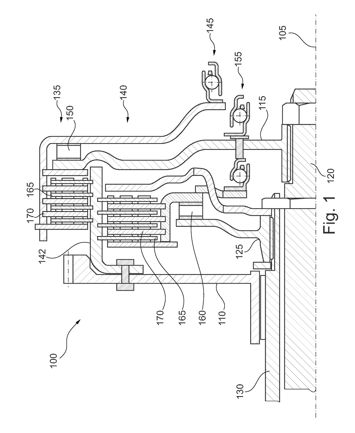
[0022]FIG. 1 shows a longitudinal section through a dual clutch device 100. An input side 110 for connecting to a drive engine, a first output side 115 for connecting to a first transmission input shaft 120, and a second output shaft 125 for connecting to a second transmission input shaft 130 are arranged about an axis of rotation 105. The transmission input shafts 120 and 130 are preferably embodied coaxially in reference to the axis of rotation 105.

[0023]A first friction clutch 135 for the production of a friction-fitting engagement between the input side 110 and the first output side 115 and a second friction clutch 140 for generating a friction-fitting engagement between the input side 110 and the second output side 125 are arranged radially offset in reference to each other. In one embodiment, selected as an example, the first friction clutch 135 is opened without actuation (“normally open”) and the second friction clutch 140 is closed without actuation (“normally closed”). In ...


PUM


Abstract

A dual clutch device having an input side, a first output side, and a second output side, which are arranged rotatably about an axis of rotation, and having a first, radially outer friction clutch for producing frictional engagement between the input side and the first output side and a second, radially inner friction clutch for producing frictional engagement between the input side and the second output side. Each friction clutch has a first friction element, which engages in the input side in a torque-transmitting manner, a second friction element, which engages in the associated output side in a torque-transmitting manner, a control element for providing an axially pressing force on the friction elements, and a leaf spring element, which is spirally wound around the axis of rotation and which is arranged axially between the control element and the friction elements.

Description

BACKGROUND[0001]The invention relates to a dual clutch. In particular the invention relates to a dual clutch for the use in a motorcycle.[0002]A dual clutch is used in connection with a dual clutch transmission in order to perform a change in gears between successive gears in a rapid and precise fashion. Here, a drive engine acts upon an input side of the dual clutch and two friction clutches that can be controlled independent from each other can each generate a frictional engagement to an allocated transmission input shaft. A pair of toothed wheels may be active at each transmission input shaft, with the pairs of toothed wheels of the different transmission input shafts usually acting upon the same output shaft. When the first clutch is opened and the second one is closed, a predetermined gear is engaged. In order to change gears, the first clutch is opened and the second one is closed.[0003]In order to transfer the technology of the dual clutch and / or the dual clutch transmission ...

Claims


Application Information

Patent Timeline
IPC IPC(8): F16D13/56F16D21/06F16D13/58
CPCF16D13/56F16D21/06F16D13/58F16D13/04F16D13/54F16D2021/0676
Inventor CHAMBRION, MARTINRUF, JOHANNES
Owner SCHAEFFLER TECH AG & CO KG
Why Eureka
Try Eureka