
Capacitive-Discharge Electromagnetic Propulsion System

a propulsion system and electromagnetic technology, applied in the direction of mechanical energy handling, mechanical equipment, machines/engines, etc., can solve the problems of unbalanced force, device not having general space-based utility, and scalability potential, and achieve full throttle range and minimal engineering

Inactive Publication Date: 2017-09-14
PURVIS JAMES WAYNE
View PDF1 Cites 5 Cited by
  • Summary
  • Abstract
  • Description
  • Claims
  • Application Information

AI Technical Summary

Benefits of technology

The present invention is an electromagnetic thruster that can generate thrust without expelling propellant. It consists of multiple capacitor assemblies, a switch-controlled conductive discharge element, multiple electromagnetic coils, and a means to generate magnetic fields with varying polarity, intensity, and duration. This invention has the advantages of minimal engineering and electric power supply complexity, and can achieve a full throttle range by controlling or varying the field strength of the electromagnetic coils or the amplitude of the discharge current.

Problems solved by technology

Another limitation to using the effect may be the scalability potential, since asymmetrical capacitor devices to date have only generated tens of milli-newtons of thrust from tens of watts of input power.
These devices do not have general space-based utility since they are restricted to operations within either the gravity field or the magnetic field of Earth.
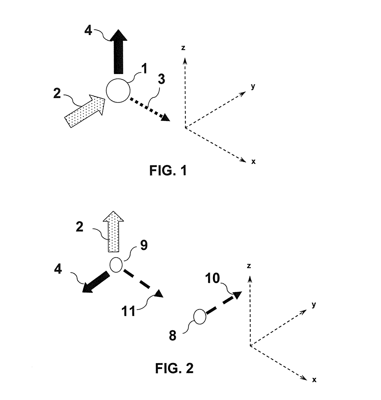
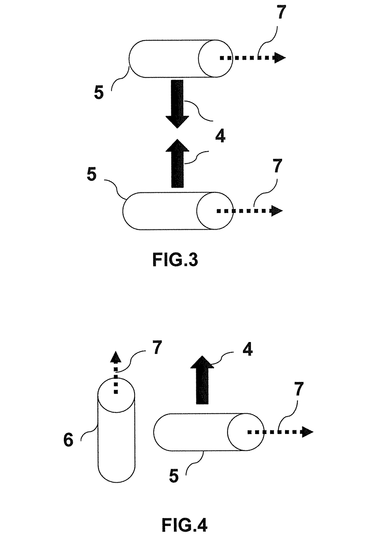
This unbalanced force arises from the fact that most individual electrons comprising the current moving in the conducting coils of the electromagnet have z-axis velocity components which are orthogonal to the x-axis velocities of each charge in the current 7.
Appropriate geometric designs with segmented current discharge paths 6 between oppositely-charged capacitor elements are exposed to external magnetic fields from electromagnetic coils in various embodiments such that unbalanced Lorentz forces are produced on the system, thereby producing thrust without expelling propellant.

Method used


Image

  • Capacitive-Discharge Electromagnetic Propulsion System
  • Capacitive-Discharge Electromagnetic Propulsion System
  • Capacitive-Discharge Electromagnetic Propulsion System

Examples


Embodiment Construction

[0039]The present invention will now be described more fully hereinafter with reference to the accompanying drawings, in which preferred embodiments of the invention are shown. This invention may, however, be embodied in many different forms and should not be construed as limited to the embodiments set forth herein. Rather, these embodiments are provided so that this disclosure will be thorough and complete, and will fully convey the scope of the invention to those skilled in the art. Like numbers refer to like elements throughout.

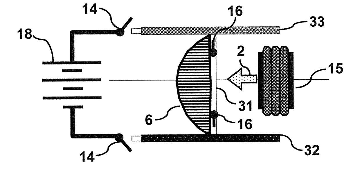
[0040]The basic operating principle of the present invention is illustrated in FIGS. 7A and 7B. In FIG. 7A, a voltage source 18 is connected through closed charge switches 14 so as to induce opposite charges on capacitor assembly elements 32 and 33. Discharge switches 16 are open, and electromagnetic coil 15 is not energized. In FIG. 7B, the voltage source 18 is disconnected by opening charge switches 14 so as to isolate the charges on capacitor assembly e...


PUM


Abstract

The present invention discloses systems and methods for electromagnetic spacecraft propulsion or thrust generation without the expulsion of reaction mass. The systems include capacitor assemblies with a switch-controlled conductive discharge path, a means of charging the capacitor assemblies, a means of generating magnetic fields using electromagnetic coils, and a means for periodically shaping the intensity, duration and polarity of magnetic fields from the coils. Thrust is generated through the interaction of the shaped magnetic fields and the segmented current in the conductive discharge path during capacitor discharge.

Description

FIELD OF THE INVENTION[0001]The present invention discloses systems and methods for electromagnetic spacecraft propulsion or thrust generation. In particular, thrust is generated without the expulsion of reaction mass. These unique systems and methods are comprised of capacitor assemblies with switch-controlled discharge elements and electromagnetic coils. The thrust is generated through the interaction of shaped magnetic fields from the coils and the current in the discharge element of the capacitor during discharge.BACKGROUND OF THE INVENTION[0002]A major issue facing future space exploration is advanced propulsion technologies. The combination of reaction mass and engine mass in traditional propulsion systems imposes practical limits to space missions. NASA and the space exploration community have addressed this problem by identifying and developing new propulsion concepts requiring either minimal or no propellant mass. The result has been the development of electric ion thruster...

Claims


Application Information

Patent Timeline
IPC IPC(8): H02K41/02
CPCH02K2207/00H02K41/02F41B6/00F03H99/00
Inventor PURVIS, JAMES WAYNE
Owner PURVIS JAMES WAYNE
Learn More