Panel-mountable fiber optic cable feedthrough

a fiber optic cable and panel mount technology, applied in the field of panel mountable fiber optic cable feedthrough, can solve the problems of increased expense, unsatisfactory use of such a structure, and difficult disassembly of such a feedthrough, and achieve the effect of tight grip, minimal effort, and no increase in the outside dimensions of the feedthrough

Inactive Publication Date: 2017-09-21
M2 OPTICS
View PDF46 Cites 14 Cited by
  • Summary
  • Abstract
  • Description
  • Claims
  • Application Information

AI Technical Summary

Benefits of technology

[0014]The complications noted above have been eliminated with several novel designs employing feedthroughs that all split open into two mating parts that can be closed around a single or multiple optical cable(s) at any desired location without the need for threading or pulling the cable(s) through one or more tight fit cylindrical cavities in the feedthrough's body. Each of the two main body parts that make up the feedthrough in such an axial-split design includes half of one or more cylindrical cavities. Simple provisions have been included to allow the two split body parts to first be loosely fit to surround the optical cable(s) and subsequently secured tightly together around the cable with minimum effort.
[0015]Strain relief for the fiber optic cable can also be incorporated into this feedthrough design in a simple manner and without increasing the feedthrough's outside dimensions or adding additional parts. In addition, a series of ribs can be formed on the inside diameter(s) of the cylindrical cavities during injection molding to ensure a very tight grip on the fiber optic patch-cord cable(s) when the two main body parts are secured together.

Problems solved by technology

But, there are some undesired complications using such a structure because it may not include the desirable feature (4) and will not include the desirable feature (5), mentioned above.
One complication with such a simple feedthrough design described above is that the fiber optic cable must be carefully threaded or pulled through a rather tight fitting cylindrical cavity in the feedthrough body and subsequently secured in place, possibly using a bonding agent or, perhaps, a compression ring that grips the fiber cable when the retaining nut(s) is tightened.
Use of a bonding agent makes disassembly of such a feedthrough difficult while use of a compression ring becomes a substantial design and production complication which increases expense.
Further, the required tight fit of the cable through the cylindrical cavity in the feedthrough would make it impractical to pass a pre-terminated fiber optic patch-cord cable due to the larger size of the optical connector relative to the cable diameter.
In addition, incorporation of some form of strain relief would be substantially more complex for a circularly symmetric designed feedthrough because its outside diameter would have to be further enlarged to accommodate a strain relief mechanism.

Method used


Image

  • Panel-mountable fiber optic cable feedthrough
  • Panel-mountable fiber optic cable feedthrough
  • Panel-mountable fiber optic cable feedthrough

Examples


Embodiment Construction

[0032]With reference to the attached drawings, embodiments of the present invention will be described in the following:

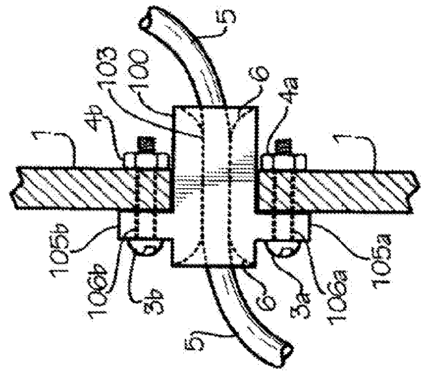
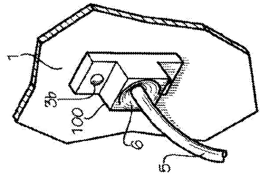
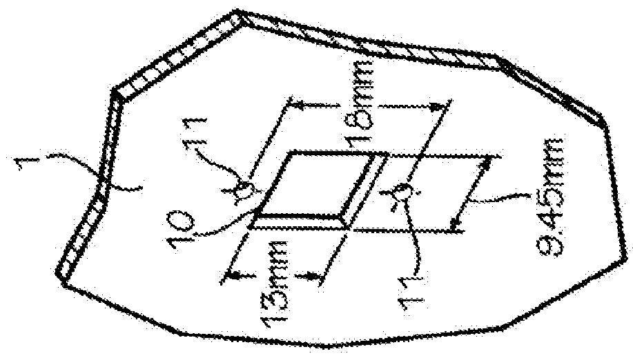
[0033]FIG. 1A shows a cross-sectional view of the basic construction and installation details of a typical panel-mounted fiber optic cable feedthrough 100. This feedthrough 100 has a lower flange 105a and an upper flange 105b each with a circular hole 106a and 106b, respectively, to accommodate two identical machine screws 3a and 3b. When the feedthrough 100 is installed in the panel 1, the machine screws 3a and 3b pass through holes 106a and 106b in the flanges 105a and 105b and then through the two holes 11 in the panel 1. The screws 3a and 3b are then secured in place by tightening matching nuts 4a and 4b or simply by rotating the screws 3a and 3b into pre-threaded holes in panel 1. This action fastens the feedthrough 100 to the panel 1. To be compatible with the standard SC mounting parts, the screws 3a and 3b should have a diameter of 2 mm and the holes 106a, 1...


PUM


Abstract

A novel panel-mountable fiber optic cable feedthrough is described that has two main body parts that can be brought together around single or multiple fiber optic cables and secured in place to prevent slippage of the cable(s). Use of two such main body parts that split along a plane that passes through the axis of the fiber optic cable(s) allows joining the two main parts at any position along the cable(s) without the need to thread the cable(s) through a one or more pre-formed cylindrical cavities in the body of the feedthrough. The main parts for this fiber optic feedthrough can be made by plastic injection molding suitably shaped to relieve bending strain in the glass optical fiber(s) within the cable(s). The foot-print for mounting such a feedthrough can be made compatible with that of a number of popular fiber optic connector mounts, including the SC-connector.

Description

CROSS REFERENCES TO RELATED APPLICATIONS[0001]This application claims the benefit of U.S. Non-Provisional patent application Ser. No. 14 / 929,703 filed Nov. 2, 2015, titled PANEL-MOUNTABLE FIBER OPTIC CABLE FEEDTHROUGH, the contents of which are hereby incorporated by reference herein.TECHNICAL FIELD AND INDUSTRIAL APPLICABILITY OF THE INVENTION[0002]This invention relates to a novel panel-mountable fiber optic cable feedthrough that has two main body parts that can be brought together around a single or multiple fiber optic cables and secured in place to prevent slippage of the cable(s).BACKGROUND OF THE INVENTION[0003]Terrestrial communications throughout the world has grown to rely heavily on optical fiber communications technology. And there is an increasing flow of signaling information that requires use of multiple optical fibers in communication links from one point to another. The various origination, termination, and relay points for optical fiber distribution systems form h...

Claims


Application Information

Patent Timeline
Patent Type & Authority Applications(United States)
IPC IPC(8): G02B6/44
CPCG02B6/4477G02B6/4459G02B6/4471
Inventor MILLER, GARY EVAN
Owner M2 OPTICS
Why Eureka
Try Eureka